Inst ToolsInst ToolsInst Tools
  • Courses
  • Automation
    • PLC
    • Control System
    • Safety System
    • Communication
    • Fire & Gas System
  • Instrumentation
    • Design
    • Pressure
    • Temperature
    • Flow
    • Level
    • Vibration
    • Analyzer
    • Control Valve
    • Switch
    • Calibration
    • Erection & Commissioning
  • Interview
    • Instrumentation
    • Electrical
    • Electronics
    • Practical
  • Q&A
    • Instrumentation
    • Control System
    • Electrical
    • Electronics
    • Analog Electronics
    • Digital Electronics
    • Power Electronics
    • Microprocessor
  • Request
Search
  • Books
  • Software
  • Projects
  • Process
  • Tools
  • Basics
  • Formula
  • Power Plant
  • Root Cause Analysis
  • Electrical Basics
  • Animation
  • Standards
  • 4-20 mA Course
  • Siemens PLC Course
Reading: Float Level Measurement
Share
Font ResizerAa
Inst ToolsInst Tools
Font ResizerAa
  • Courses
  • Design
  • PLC
  • Interview
  • Control System
Search
  • Courses
  • Automation
    • PLC
    • Control System
    • Safety System
    • Communication
    • Fire & Gas System
  • Instrumentation
    • Design
    • Pressure
    • Temperature
    • Flow
    • Level
    • Vibration
    • Analyzer
    • Control Valve
    • Switch
    • Calibration
    • Erection & Commissioning
  • Interview
    • Instrumentation
    • Electrical
    • Electronics
    • Practical
  • Q&A
    • Instrumentation
    • Control System
    • Electrical
    • Electronics
    • Analog Electronics
    • Digital Electronics
    • Power Electronics
    • Microprocessor
  • Request
Follow US
All rights reserved. Reproduction in whole or in part without written permission is prohibited.
Inst Tools > Blog > Level Measurement > Float Level Measurement

Float Level Measurement

Last updated: December 30, 2018 9:21 pm
Editorial Staff
Level Measurement
No Comments
Share
6 Min Read
SHARE

Float Level Measurement

Perhaps the simplest form of solid or liquid level measurement is with a float : a device that rides on the surface of the fluid or solid within the storage vessel. The float itself must be of substantially lesser density than the substance of interest, and it must not corrode or otherwise react with the substance.

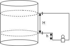
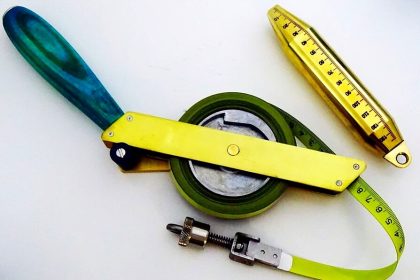
Floats may be used for manual “gauging” of level, as illustrated here:

Level Measurement using Float

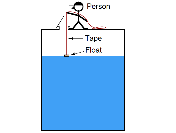
A person lowers a float down into a storage vessel using a flexible measuring tape, until the tape goes slack due to the float coming to rest on the material surface. At that point, the person notes the length indicated on the tape (reading off the lip of the vessel access hole). This distance is called the ullage, being the distance from the top of the vessel to the surface of the process material. Fillage of the vessel may be determined by subtracting this “ullage” measurement from the known height of the vessel.

Obviously, this method of level measurement is tedious and may pose risk to the person conducting the measurement. If the vessel is pressurized, this method is simply not applicable.

Also Read : TDR & FMCW Radar Level Transmitters Principle

If we automate the person’s function using a small winch controlled by a electronic control – having the electronic control automatically lower the float down to the material surface and measure the amount of cable played out at each measurement cycle – we may achieve better results without human intervention. Such a level gauge may be enclosed in such a way to allow pressurization of the vessel, too:

Cable Float Principle

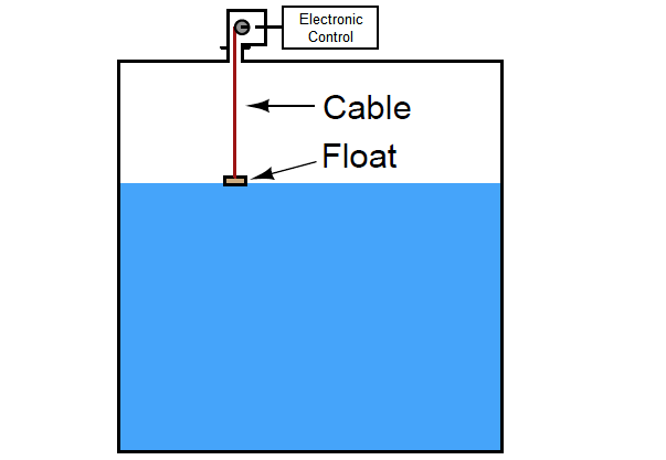
A simpler version of this technique uses a spring-reel to constantly tension the cable holding the float, such that the float continuously rides on the surface of the liquid in the vessel.

Cable Float Level Theory

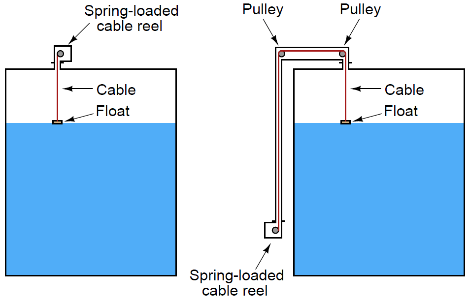
Note : A spring-loaded cable float only works with liquid level measurement, while a retracting float will measure liquids and solids with equal ease. The reason for this limitation is simple: a float that always contacts the material surface is likely to become buried if the material in question is a solid (powder or granules), which must be fed into the vessel from above.

The following photograph shows the “measurement head” of a spring-reel tape-and-float liquid level transmitter, with the vertical pipe housing the tape on its way to the top of the storage tank where it will turn 180 degrees via two pulleys and attach to the float inside the tank:

spring-reel tape-and-float liquid

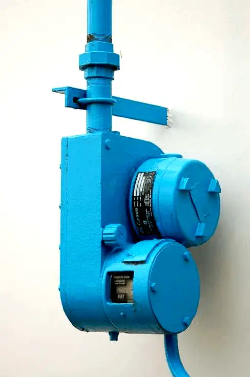
The spring reel’s angular position may be measured by a multi-turn potentiometer or a rotary encoder (located inside the “head” unit), then converted to an electronic signal for transmission to a remote display, control, and/or recording system. Such systems are used extensively for measurement of water and fuel in storage tanks.

If the liquid inside the vessel is subject to turbulence, guide wires may be necessary to keep the float cable in a vertical orientation:

Guide Wire Level Measurement

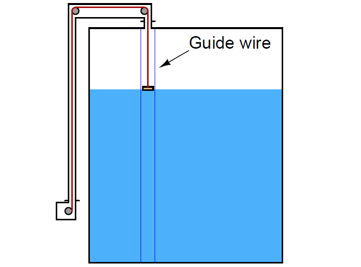
The guide wires are anchored to the floor and roof of the vessel, passing through ring lugs on the float to keep it from straying laterally. One of the potential disadvantages of tape-and-float level measurement systems is fouling of the tape (and guide wires) if the substance is sticky or unclean. A variation on the theme of float level measurement is to place a small float inside the tube of a sightglass-style level gauge:

Float Level Gauge Working

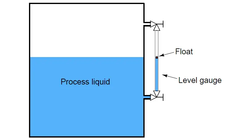
The float’s position inside the tube may be readily detected by ultrasonic waves, magnetic sensors or any other applicable means. Locating the float inside a tube eliminates the need for guide wires or a sophisticated tape retraction or tensioning system. If no visual indication is necessary, the level gauge tube may be constructed out of metal instead of glass, greatly reducing the risk of tube breakage. All the problems inherent to sight glasses, however, still apply to this form of float instrument.

The following photograph shows just such a float-style level indicator, manufactured by KTek. This particular level indicator is removed from the process, sitting on a concrete floor for the photograph. A magnetic float rides on the surface of a liquid column inside a non-magnetic metal tube, while a brightly-colored indicating flag tracks the magnetic float’s position inside a transparent plastic tube for convenient viewing:

Float Level Gauge Installation

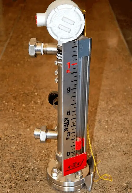
Two major advantages of a magnetically-coupled float is increased pressure rating and safety (since the float tube need not be constructed of clear material such as plastic or glass), and increased readability (since the viewing tube will never get dirty with process fluid residue, and the float may be brightly colored).

Also Read : Overview of Tank Gauging Technologies

Credits : by Tony R. Kuphaldt – Creative Commons Attribution 4.0 License

Don't Miss Our Updates
Be the first to get exclusive content straight to your email.
We promise not to spam you. You can unsubscribe at any time.
Invalid email address
You've successfully subscribed !

Continue Reading

DP Transmitter Dry Leg & Wet Leg Calculations
Differential Pressure (DP) Level transmitter Installed Above Tapping Point
How can we use a DP Flow Transmitter for Level Measurement
Float Level Switch Working Principle Animation
Microwave Barrier Level Switch Working Principle
Closed Tank Level Measurement using DP Transmitters
Share This Article
Facebook Whatsapp Whatsapp LinkedIn Copy Link
Share
Leave a Comment

Leave a Reply Cancel reply

Your email address will not be published. Required fields are marked *

Stay Connected

128.3kFollowersLike
69.1kFollowersFollow
210kSubscribersSubscribe
38kFollowersFollow

Categories

Explore More

Comparison of Level Meters – Level Measurement Instruments
Remote Seal Transmitters Ranging Calculation
Magnetostrictive Tank Gauging (MTG)
Capacitance Level Switch Working Principle
Closed Tank Remote Seal Capillary type DP Transmitter
Potentiometric Level Measurement Principle
Contact and Non-Contact Level Sensors
Tank Level Detection Switches

Keep Learning

Nuclear Level Measurement

Nuclear Level Detectors Cascade or Master/Slave concept

Level Transmitters Auto Calibration

DP Level Transmitter Auto Calibration

Magnetostrictive Level Transmitter Calibration

Magnetostrictive Level Transmitter Calibration Procedure

Calibrating Transmitter System One Seal with suppressed Zero

Calibrating Level Transmitter with Remote Seals

Practical Level Sensors Questions and Answers

Practical Level Sensors Questions and Answers

Servo Operated Float Level Measurement

Servo Operated Float Level Measurement

Calibration Procedure of displacer type Level transmitter

Calibration of Displacer Level Transmitter

guided-wave radar Transmitter Setup

Guided-Wave Radar Instruments Diagnostics

Learn More

Electrical Machines Objective Questions

Electrical Machines MCQ Series 22

IEC Area Classification System

Ex ic Intrinsic safety Standard

Air Pressure Regulator cut-away diagram

Air Pressure Regulator Questions

Gas flow rate Formulas

Gas Flow Formulas

Allen-Bradley VFD

Why V/f Ratio is kept Constant in VFD?

Control Algorithms in PLC Programming

Control Algorithms in PLC Programming

PLC Programming for Automated Curtain Control

Automatic Curtain Control – PLC Programming Solution

Shaper Machine Hydraulic Circuit Design

Hydraulic Shaper Machine – Components, Circuit, Principle

Menu

  • About
  • Privacy Policy
  • Copyright

Quick Links

  • Learn PLC
  • Helping Hand
  • Part Time Job

YouTube Subscribe

Follow US
All rights reserved. Reproduction in whole or in part without written permission is prohibited.
Welcome Back!

Sign in to your account

Username or Email Address
Password

Lost your password?