Inst ToolsInst ToolsInst Tools
  • Courses
  • Automation
    • PLC
    • Control System
    • Safety System
    • Communication
    • Fire & Gas System
  • Instrumentation
    • Design
    • Pressure
    • Temperature
    • Flow
    • Level
    • Vibration
    • Analyzer
    • Control Valve
    • Switch
    • Calibration
    • Erection & Commissioning
  • Interview
    • Instrumentation
    • Electrical
    • Electronics
    • Practical
  • Q&A
    • Instrumentation
    • Control System
    • Electrical
    • Electronics
    • Analog Electronics
    • Digital Electronics
    • Power Electronics
    • Microprocessor
  • Request
Search
  • Books
  • Software
  • Projects
  • Process
  • Tools
  • Basics
  • Formula
  • Power Plant
  • Root Cause Analysis
  • Electrical Basics
  • Animation
  • Standards
  • 4-20 mA Course
  • Siemens PLC Course
Reading: Draw Wiring of a Pressure Switch to control two lamps
Share
Font ResizerAa
Inst ToolsInst Tools
Font ResizerAa
  • Courses
  • Design
  • PLC
  • Interview
  • Control System
Search
  • Courses
  • Automation
    • PLC
    • Control System
    • Safety System
    • Communication
    • Fire & Gas System
  • Instrumentation
    • Design
    • Pressure
    • Temperature
    • Flow
    • Level
    • Vibration
    • Analyzer
    • Control Valve
    • Switch
    • Calibration
    • Erection & Commissioning
  • Interview
    • Instrumentation
    • Electrical
    • Electronics
    • Practical
  • Q&A
    • Instrumentation
    • Control System
    • Electrical
    • Electronics
    • Analog Electronics
    • Digital Electronics
    • Power Electronics
    • Microprocessor
  • Request
Follow US
All rights reserved. Reproduction in whole or in part without written permission is prohibited.
Inst Tools > Blog > Instrumentation Design > Draw Wiring of a Pressure Switch to control two lamps

Draw Wiring of a Pressure Switch to control two lamps

Last updated: August 20, 2017 6:59 am
Editorial Staff
Instrumentation Design Practical Questions
No Comments
Share
1 Min Read
SHARE

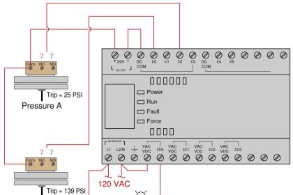
Sketch the necessary wiring to make this pressure switch control two lamps in the following manner:

  • High process pressure: green lamp on and red lamp off
  • •Low process pressure: red lamp on and green lamp of

pressure switch control two lamps

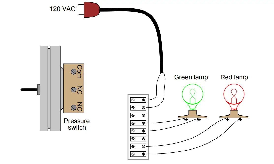
Hint: remember that the “normal” status of a switch is defined as the status of minimum stimulus: when the switch is exposed to the lowest possible degree of process stimulation (in this particular case, to the lowest possible pressure).
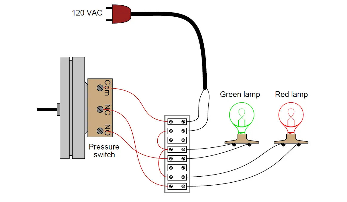
Answer :

This is just one possible solution:

pressure switch control two lamps wiring

Share Your Answer / Comments

Credits : by Tony R. Kuphaldt – under CC BY 1.0

Don't Miss Our Updates
Be the first to get exclusive content straight to your email.
We promise not to spam you. You can unsubscribe at any time.
Invalid email address
You've successfully subscribed !

Continue Reading

Design View of Supplying Process Control and Safety Systems
I&C Engineer Roles & Responsibilities – Instrumentation Design
Types of Cables, Purpose, Advantages, Disadvantages, Applications
Air Pressure Regulator Questions
Single and Three Phase Immersion Electrical Heaters Wiring Circuits
Questions on Resistive Tape Level Sensor
Share This Article
Facebook Whatsapp Whatsapp LinkedIn Copy Link
Share
Leave a Comment

Leave a Reply Cancel reply

Your email address will not be published. Required fields are marked *

Stay Connected

128.3kFollowersLike
69.1kFollowersFollow
210kSubscribersSubscribe
38kFollowersFollow

Categories

Explore More

Instrument Air Quality
Instrument Junction Box Specification
Steam Tracing
Basic Calculations of Instrument Air
Air Cylinder Consumption Calculation for Control Valves
Determine Calibration Range of Pneumatic Pressure Transmitter
Diaphragm Seal Material Selection
How to Prepare Pressure Gauge Datasheet ?

Keep Learning

Pneumatic Piping Design and Specification

Pneumatic Piping Design and Specification

Steam Eductor Question

A Series of False Pressure Alarms

Instrument Loop Diagram

How-to Create Instrument Loop Diagram (ILD)?

Cable Trays

Types of Cable Trays – Purpose, Advantages, Disadvantages

Fail Safe Switch Circuit

Basics of Fail-safe Circuits

liquid flow control loop

Liquid Flow Control Loop Controller Action

How to Select a pH and ORP Meter

How to Select a pH or ORP Meter

Practical Control Systems Questions & Answers

Practical Process Control System Questions & Answers – 3

Learn More

strain gauge with Diaphragm

Strain Gauge Working Principle

Forward reverse motor control diagram with timer

Timer during Motor Direction Change PLC Program

Transformer Efficiency

Transformer Efficiency

Fieldbus Pressure Transmitter Configuration

Foundation Fieldbus Pressure Transmitter Configuration

Thermocouple simulator

Problems of Reference Junction Compensation : Thermocouples

Pressure Transmitter Impulse Lines Heat Trace

Pressure Transmitters Heat-traced impulse lines

Advantages & Disadvantages of AC power and DC power

Advantages & Disadvantages of AC power and DC power

Voltage Polarities

Voltage Polarity and Current Direction

Menu

  • About
  • Privacy Policy
  • Copyright

Quick Links

  • Learn PLC
  • Helping Hand
  • Part Time Job

YouTube Subscribe

Follow US
All rights reserved. Reproduction in whole or in part without written permission is prohibited.
Welcome Back!

Sign in to your account

Username or Email Address
Password

Lost your password?