Inst ToolsInst ToolsInst Tools
  • Courses
  • Automation
    • PLC
    • Control System
    • Safety System
    • Communication
    • Fire & Gas System
  • Instrumentation
    • Design
    • Pressure
    • Temperature
    • Flow
    • Level
    • Vibration
    • Analyzer
    • Control Valve
    • Switch
    • Calibration
    • Erection & Commissioning
  • Interview
    • Instrumentation
    • Electrical
    • Electronics
    • Practical
  • Q&A
    • Instrumentation
    • Control System
    • Electrical
    • Electronics
    • Analog Electronics
    • Digital Electronics
    • Power Electronics
    • Microprocessor
  • Request
Search
  • Books
  • Software
  • Projects
  • Process
  • Tools
  • Basics
  • Formula
  • Power Plant
  • Root Cause Analysis
  • Electrical Basics
  • Animation
  • Standards
  • 4-20 mA Course
  • Siemens PLC Course
Reading: Diode Clampers Principle
Share
Font ResizerAa
Inst ToolsInst Tools
Font ResizerAa
  • Courses
  • Design
  • PLC
  • Interview
  • Control System
Search
  • Courses
  • Automation
    • PLC
    • Control System
    • Safety System
    • Communication
    • Fire & Gas System
  • Instrumentation
    • Design
    • Pressure
    • Temperature
    • Flow
    • Level
    • Vibration
    • Analyzer
    • Control Valve
    • Switch
    • Calibration
    • Erection & Commissioning
  • Interview
    • Instrumentation
    • Electrical
    • Electronics
    • Practical
  • Q&A
    • Instrumentation
    • Control System
    • Electrical
    • Electronics
    • Analog Electronics
    • Digital Electronics
    • Power Electronics
    • Microprocessor
  • Request
Follow US
All rights reserved. Reproduction in whole or in part without written permission is prohibited.
Inst Tools > Blog > Electronic Devices & Circuits > Diode Clampers Principle

Diode Clampers Principle

Last updated: October 5, 2016 12:44 pm
Editorial Staff
Electronic Devices & Circuits
No Comments
Share
2 Min Read
SHARE

A clamper adds a dc level to an ac voltage. Clampers are sometimes known as dc restorers. Below Figure shows a diode clamper that inserts a positive dc level in the output wave form. The operation of this circuit can be seen by considering the first negative half-cycle of the input voltage.

When the input voltage initially goes negative, the diode is forward biased, allowing the capacitor to charge to near the peak of the input (Vp(in) – 0.7 V), as shown in Figure (a). Just after the negative peak, the diode is reverse-biased. This is because the cathode is held near Vp(in) – 0.7 V by the charge on the capacitor. The capacitor can only discharge through the high resistance of RL. So, from the peak of one negative half-cycle to the next, the capacitor discharges very little. The amount that is discharged, of course, depends on the value of RL.

diode-clamper-circuit

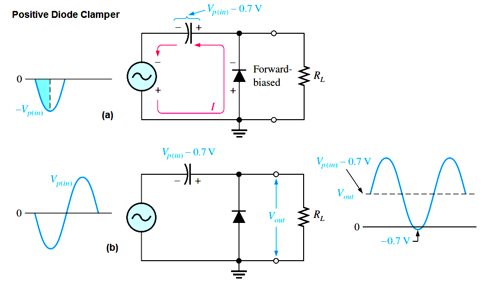
Fig : Positive Diode Clamper Operation

If the capacitor discharges during the period of the input wave, clamping action is affected. If the RC time constant is 100 times the period, the clamping action is excellent. An RC time constant of ten times the period will have a small amount of distortion at the ground level due to the charging current.

The net effect of the clamping action is that the capacitor retains a charge approximately equal to the peak value of the input less the diode drop. The capacitor voltage acts essentially as a battery in series with the input voltage. The dc voltage of the capacitor adds to the input voltage by superposition, as in Above Figure. If the diode is turned around, a negative dc voltage is added to the input voltage to produce the output voltage as shown in Below Figure.

Negative Diode Clamper Operation

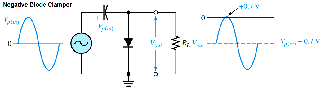
Fig : Negative Diode Clamper Operation

Don't Miss Our Updates
Be the first to get exclusive content straight to your email.
We promise not to spam you. You can unsubscribe at any time.
Invalid email address
You've successfully subscribed !

Continue Reading

How to Test a Diode using Multimeter
Series and Parallel Resistors
Capacitor Filter Working Principle
Ideal Diode Characteristics
Basic Transistor Amplifier Circuit Principle
Dependent Voltage Source
Share This Article
Facebook Whatsapp Whatsapp LinkedIn Copy Link
Share
Leave a Comment

Leave a Reply Cancel reply

Your email address will not be published. Required fields are marked *

Stay Connected

128.3kFollowersLike
69.1kFollowersFollow
210kSubscribersSubscribe
38kFollowersFollow

Categories

Explore More

Resistors Principle & Applications
Comparison of MOSFET and BJT
Transistor Collector Feedback Bias
Circuit Elements and Types of Circuits
JFET Working Animation
Limitations of Resistors
Classification of Bridge Circuits
Applications of Photo diodes

Keep Learning

Current Divider Rule

Current Divider Rule

Insulators, Conductors and Semiconductors

Peak Inverse Voltage of Center Tap Rectifier

Peak Inverse Voltage of Center Tap Rectifier

Transistor Biasing

Transistor Biasing

half-wave-voltage-doubler-using-diodes

Half Wave Voltage Doubler using Diodes

energy-diagrams-for-insulator-semiconductor-and-conductor

Band Gap for Semiconductor Materials

full-wave-bridge-rectifier-with-voltage-regulator

Basics of Voltage Regulators

Transistor Emitter Feedback Bias

Transistor Emitter Feedback Bias

Learn More

Non‐contact RADAR Level Transmitter Pulse

Non Contact RADAR Level Transmitter Principle, Limitations, Design, Installation and Calibration

Understanding RS-485 Communication

Understanding RS-485 Communication

Why Measure Level

Digital Electronics Multiple Choice Questions

Memory Devices Objective Questions – Part 4

Dependent Current Source

Dependent Current Source

Architecture of Allen Bradley PLC

Architecture of Allen Bradley PLC

ORP Measurement

Basics of ORP Measurement

thermocouple voltages

Manually Interpreting Thermocouple Voltages

Menu

  • About
  • Privacy Policy
  • Copyright

Quick Links

  • Learn PLC
  • Helping Hand
  • Part Time Job

YouTube Subscribe

Follow US
All rights reserved. Reproduction in whole or in part without written permission is prohibited.
Welcome Back!

Sign in to your account

Username or Email Address
Password

Lost your password?