Inst ToolsInst ToolsInst Tools
  • Courses
  • Automation
    • PLC
    • Control System
    • Safety System
    • Communication
    • Fire & Gas System
  • Instrumentation
    • Design
    • Pressure
    • Temperature
    • Flow
    • Level
    • Vibration
    • Analyzer
    • Control Valve
    • Switch
    • Calibration
    • Erection & Commissioning
  • Interview
    • Instrumentation
    • Electrical
    • Electronics
    • Practical
  • Q&A
    • Instrumentation
    • Control System
    • Electrical
    • Electronics
    • Analog Electronics
    • Digital Electronics
    • Power Electronics
    • Microprocessor
  • Request
Search
  • Books
  • Software
  • Projects
  • Process
  • Tools
  • Basics
  • Formula
  • Power Plant
  • Root Cause Analysis
  • Electrical Basics
  • Animation
  • Standards
  • 4-20 mA Course
  • Siemens PLC Course
Reading: Difference between Current Transformer and Potential Transformer
Share
Font ResizerAa
Inst ToolsInst Tools
Font ResizerAa
  • Courses
  • Design
  • PLC
  • Interview
  • Control System
Search
  • Courses
  • Automation
    • PLC
    • Control System
    • Safety System
    • Communication
    • Fire & Gas System
  • Instrumentation
    • Design
    • Pressure
    • Temperature
    • Flow
    • Level
    • Vibration
    • Analyzer
    • Control Valve
    • Switch
    • Calibration
    • Erection & Commissioning
  • Interview
    • Instrumentation
    • Electrical
    • Electronics
    • Practical
  • Q&A
    • Instrumentation
    • Control System
    • Electrical
    • Electronics
    • Analog Electronics
    • Digital Electronics
    • Power Electronics
    • Microprocessor
  • Request
Follow US
All rights reserved. Reproduction in whole or in part without written permission is prohibited.
Inst Tools > Blog > Electrical Basics > Difference between Current Transformer and Potential Transformer

Difference between Current Transformer and Potential Transformer

Last updated: September 19, 2016 1:51 am
Editorial Staff
Electrical Basics
No Comments
Share
2 Min Read
SHARE

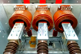
Current Transformers (CT) and Potential Transformers (PT) are used to measure the current and voltage in a circuit of the order of hundreds of amperes and volts respectively.

A CT has large number of turns on its secondary winding, but very few turns on its primary winding. The primary winding is connected in series with the load so that it carries full load current. A low voltage range ammeter (0-5A) is connected across the secondary winding terminals. Secondary of the CT is practically short circuited since the ammeter resistance is very low. It should be remembered that secondary of the CT should not be made open as it draws heavy current and damages the primary winding of the CT

A PT has large number of turns in the primary and fewer turns in the secondary and hence it steps down the voltage. The primary winding is connected across the supply voltage and low range voltmeter (0-110V) is connected across the secondary winding terminals

Some of the main difference between current transformers (CT) and potential transformers (PT) are given below:

  • The secondary of the CT is almost short circuit, whereas the secondary of the PT is practically a open circuit
  • The primary winding of the CT is connected in series with the load so that it carries the full line current, but there is only a small voltage across it. However the primary winding of the PT has the full supply voltage applied across it
  • In CT the excitation current I0 and flux density vary over a wide range whereas in PT, they vary over a limited range only

Don't Miss Our Updates
Be the first to get exclusive content straight to your email.
We promise not to spam you. You can unsubscribe at any time.
Invalid email address
You've successfully subscribed !

Continue Reading

How to Test a Motor using Megger?
Difference between Servo Motor and DC Motor
Circuit Breaker Testing – Routine Tests of Circuit Breakers
Basics of Electricity Rates
Root Cause Analysis – Burst Transformers and 11 kV Input Breakers
Automatic Transfer Switch – Electrical Circuit, Operation, Video
Share This Article
Facebook Whatsapp Whatsapp LinkedIn Copy Link
Share
Leave a Comment

Leave a Reply Cancel reply

Your email address will not be published. Required fields are marked *

Stay Connected

128.3kFollowersLike
69.1kFollowersFollow
210kSubscribersSubscribe
38kFollowersFollow

Categories

Explore More

Difference between AC and DC
What is Transformer Bushing? Working Principle
What is a Solid State Relay? – Working Principle, Types of Control
Types of Relays used in an Air Circuit Breaker (ACB)
Most Asked Questions on Servo Motor (Answers)
Difference Between Circuit Breaker and Disconnector
Difference Between Earth and Neutral
Difference Between Short Circuit and Ground Fault

Keep Learning

Types of Filters used in Air Compressors

How Do Air Compressor Filters Clean and Protect the System?

How do AC drives work

How do AC Drives Work? – Variable Frequency Drive (VFD)

Wave Trap in Power Line carrier Communication

What is a Wave Trap? – Power Line Carrier Communication

How to Read and Understand an Electrical Single Line Diagram?

How to Read and Understand an Electrical Single Line Diagram?

What is Electrical Panel Door Earth Bonding? Explained

What is Electrical Panel Door Earth Bonding? Explained

Lithium-ion Battery Charging System

Lithium-ion Battery Charging Systems

Typical Switchyard Layout

Electrical Substation – Busbar Arrangements and Layouts

Electrical Equipment Selection in Hazardous Area

Hazardous Areas in Industry – Electrical Equipment Selection

Learn More

Siemens PLC Organization Blocks used For Troubleshooting

Tia Portal – OB121 Programming Errors Interrupt Organization Block

Transformer Protection using fire water spray system

Fire Water Spray Systems Principle

Weir Diaphragm Valve

Diaphragm Valves Construction, Types, Stem & Bonnet Assembly

diodes-questions-answers

Diodes Questions & Answers

Analog Measurement using Ladder Logic

Analog Measurement using Ladder Logic

DCS System Cabinet

Yokogawa DCS System Maintenance Procedures

Lead Acid Battery Operation

How does a Lead Acid Battery Work?

Electrical Resistance Temperature Curves of RTD

Resistance Temperature Detectors (RTD) Construction

Menu

  • About
  • Privacy Policy
  • Copyright

Quick Links

  • Learn PLC
  • Helping Hand
  • Part Time Job

YouTube Subscribe

Follow US
All rights reserved. Reproduction in whole or in part without written permission is prohibited.
Welcome Back!

Sign in to your account

Username or Email Address
Password

Lost your password?