Foundation Fieldbus
FOUNDATION Fieldbus is an all-digital, serial, two-way communications system that serves as the base-level network in a plant or factory automation environment. It is an open architecture, developed and administered by the Fieldbus Foundation.
Main Differences:
- Is designed to address the needs of process automation.
- Foundation Fieldbus H1 uses the physical layer as defined in IEC 1158-2.
- Supports the requirements of intrinsic safety, including the new FISCO model.
- A peer-to-peer protocol. Devices can communicate with each other without a host and they can initiate communications without a specific host command.
- Control can be in the field device, or the host, or partially in both.
- When control is in the field devices, the host can be disconnected without halting the loop.
- Addresses interoperability by a combination of device descriptions and function blocks. A single host application can configure and access all device information and functionality.
- It uses device description technology to make all information available to all devices, host systems, and applications.
- The device address can be manually/ automatically assigned. It uses a special message to detect and identify a new device. A device can be added or deleted when the segment is in operation.
- It supports device and function block tags in the field devices. Thus, a device can be located by simply asking for it by its tag.
- Provides a distributed real-time clock on the bus.
- It is appropriate for real-time control on the bus—with or without a host.
More Details :
Two related implementations of FOUNDATION fieldbus have been introduced to meet different needs within the process automation environment. These two implementations use different physical media and communication speeds.
- FOUNDATION Fieldbus H1 – Operates at 31.25 kbit/s and is generally used to connect to field devices and host systems. It provides communication and power over standard stranded twisted-pair wiring in both conventional and intrinsic safety applications. H1 is currently the most common implementation.
- HSE (High-speed Ethernet) – Operates at 100/1000 Mbit/s and generally connects input/output subsystems, host systems, linking devices and gateways. It doesn’t currently provide power over the cable, although work is under way to address this using the IEEE802.3af Power over Ethernet (PoE) standard.
FOUNDATION fieldbus was originally intended as a replacement for the 4-20 mA standard, and today it coexists alongside other technologies such as Modbus, Profibus, and Industrial Ethernet. FOUNDATION fieldbus today enjoys a growing installed base in many heavy process applications such as refining, petrochemicals, power generation, and even food and beverage, pharmaceuticals, and nuclear applications. FOUNDATION fieldbus was developed over a period of many years by the International Society of Automation, or ISA, as SP50. In 1996 the first H1 (31.25 kbit/s) specifications were released. In 1999 the first HSE (High Speed Ethernet) specifications were released. The International Electrotechnical Commission (IEC) standard on field bus, including FOUNDATION Fieldbus, is IEC 61158. Type 1 is FOUNDATION Fieldbus H1, while Type 5 is FOUNDATION Fieldbus HSE.
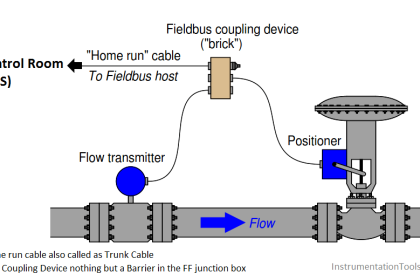
A typical fieldbus segment consists of the following components.
- H1 card – fieldbus interface card (It is common practice to have redundant H1 cards, but ultimately this is application specific)
- PS – Bulk power (Vdc) to Fieldbus Power Supply
- FPS – Fieldbus Power Supply and Signal Conditioner (Integrated power supplies and conditioners have become the standard nowadays)
- T – Terminators (Exactly 2 terminators are used per fieldbus segment. One at the FPS and one at the furthest point of a segment at the device coupler)
- LD – Linking Device, alternatively used with HSE networks to terminate 4-8 H1 segments acting as a gateway to an HSE backbone network.
- And fieldbus devices, (e.g. transmitters, transducers, etc.)
PROFIBUS
PROFIBUS (Process Field Bus) is a standard for fieldbus communication in automation technology and was first promoted in 1989 by BMBF(German department of education and research) and then used by Siemens. It should not be confused with the PROFINET standard for Industrial Ethernet. PROFIBUS is openly published as part of IEC 61158.
Main Differences:
- Is designed to address the needs of discrete manufacturing and building automation.
- PROFIBUS-PA uses the physical layer as defined in IEC 1158-2.
- Supports the requirements of intrinsic safety, including the new FISCO model.
- PROFIBUS-PA is a master–slave protocol. A field device is a slave and it can only respond to a command from the master.
- With PROFIBUS-PA, control resides only in the host.
- Host must be present for control to function.
- A PROFIBUS-PA host uses a standard profile for basic functionality. For additional vendor-specific functionality, the host must have the corresponding software.
- The device configuration and management host use device descriptions to configure and interact with the device. The control host uses profiles to access device information.
- Device addresses are set by setting DIP switches or user-entered software addresses. To add a device, the segment must be shut, and the device address and configuration parameters are configured in the host. The segment is then restarted.
- It supports tag in the host. Tag data base is manually entered in the host.
- Does not provide a real-time clock on the bus.
- Appropriate for host-based control only.
More details
The history of PROFIBUS goes back to a publicly promoted plan for an association which started in Germany in 1986 and for which 21 companies and institutes devised a master project plan called “fieldbus”. The goal was to implement and spread the use of a bit-serial field bus based on the basic requirements of the field device interfaces. For this purpose, member companies agreed to support a common technical concept for production (i.e. discrete or factory automation) and process automation.
First, the complex communication protocol Profibus FMS (Field bus Message Specification), which was tailored for demanding communication tasks, was specified. Subsequently in 1993, the specification for the simpler and thus considerably faster protocol PROFIBUS DP (Decentralised Peripherals) was completed. Profibus FMS is used for (non-deterministic) communication of data between Profibus Masters. Profibus DP is a protocol made for (deterministic) communication between Profibus masters and their remote I/O slaves.
There are two variations of PROFIBUS in use today; the most commonly used PROFIBUS DP, and the lesser used, application specific, PROFIBUS PA:
- PROFIBUS DP (Decentralised Peripherals) is used to operate sensors and actuators via a centralised controller in production (factory) automation applications. The many standard diagnostic options, in particular, are focused on here.
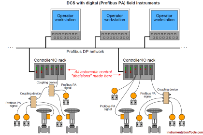
- PROFIBUS PA (Process Automation) is used to monitor measuring equipment via a process control system in process automation applications. This variant is designed for use in explosion/hazardous areas (Ex-zone 0 and 1). The Physical Layer (i.e. the cable) conforms to IEC 61158-2, which allows power to be delivered over the bus to field instruments, while limiting current flows so that explosive conditions are not created, even if a malfunction occurs. The number of devices attached to a PA segment is limited by this feature. PA has a data transmission rate of 31.25 kbit/s. However, PA uses the same protocol as DP, and can be linked to a DP network using a coupler device. The much faster DP acts as a backbone network for transmitting process signals to the controller. This means that DP and PA can work tightly together, especially in hybrid applications where process and factory automation networks operate side by side.


what is peer-to-peer protocol ?