Inst ToolsInst ToolsInst Tools
  • Courses
  • Automation
    • PLC
    • Control System
    • Safety System
    • Communication
    • Fire & Gas System
  • Instrumentation
    • Design
    • Pressure
    • Temperature
    • Flow
    • Level
    • Vibration
    • Analyzer
    • Control Valve
    • Switch
    • Calibration
    • Erection & Commissioning
  • Interview
    • Instrumentation
    • Electrical
    • Electronics
    • Practical
  • Q&A
    • Instrumentation
    • Control System
    • Electrical
    • Electronics
    • Analog Electronics
    • Digital Electronics
    • Power Electronics
    • Microprocessor
  • Request
Search
  • Books
  • Software
  • Projects
  • Process
  • Tools
  • Basics
  • Formula
  • Power Plant
  • Root Cause Analysis
  • Electrical Basics
  • Animation
  • Standards
  • 4-20 mA Course
  • Siemens PLC Course
Reading: Choke Input Filter Operation
Share
Font ResizerAa
Inst ToolsInst Tools
Font ResizerAa
  • Courses
  • Design
  • PLC
  • Interview
  • Control System
Search
  • Courses
  • Automation
    • PLC
    • Control System
    • Safety System
    • Communication
    • Fire & Gas System
  • Instrumentation
    • Design
    • Pressure
    • Temperature
    • Flow
    • Level
    • Vibration
    • Analyzer
    • Control Valve
    • Switch
    • Calibration
    • Erection & Commissioning
  • Interview
    • Instrumentation
    • Electrical
    • Electronics
    • Practical
  • Q&A
    • Instrumentation
    • Control System
    • Electrical
    • Electronics
    • Analog Electronics
    • Digital Electronics
    • Power Electronics
    • Microprocessor
  • Request
Follow US
All rights reserved. Reproduction in whole or in part without written permission is prohibited.
Inst Tools > Blog > Electronic Devices & Circuits > Choke Input Filter Operation

Choke Input Filter Operation

Last updated: September 27, 2016 3:50 pm
Editorial Staff
Electronic Devices & Circuits
No Comments
Share
1 Min Read
SHARE

The below Fig. shows a typical choke input filter circuit.  It consists of a Choke L connected in series with the rectifier output and a filter capacitor C across the load. Only a single filter section is shown, but several identical sections are often used to reduce the pulsations as effectively as possible.

Choke Input Filter Operation

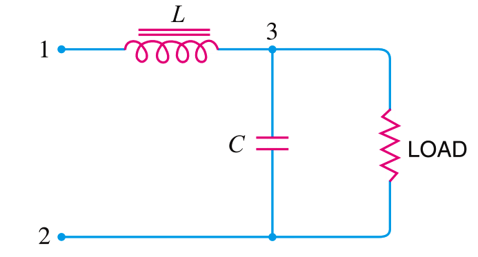
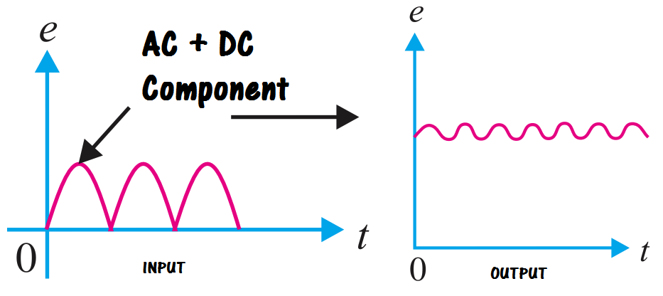
The pulsating output of the rectifier is applied across terminals 1 and 2 of the filter circuit.  As discussed before, the pulsating output of rectifier contains a.c. and d.c. components.  The choke offers high opposition to the passage of a.c. component but negligible opposition to the d.c. component.  The result is that most of the a.c. component appears across the choke while whole of d.c. component passes through the choke on its way to load.  This results in the reduced pulsations at terminal 3.

inductor-filter-output

inductor-principle

Don't Miss Our Updates
Be the first to get exclusive content straight to your email.
We promise not to spam you. You can unsubscribe at any time.
Invalid email address
You've successfully subscribed !

Continue Reading

Half Wave Voltage Doubler using Diodes
Circuit Elements and Types of Circuits
Optoisolator Working Principle
PMMC Temperature Compensation
Light Emitting Diode Operation
Transistor Load Line Analysis
Share This Article
Facebook Whatsapp Whatsapp LinkedIn Copy Link
Share
Leave a Comment

Leave a Reply Cancel reply

Your email address will not be published. Required fields are marked *

Stay Connected

128.3kFollowersLike
69.1kFollowersFollow
210kSubscribersSubscribe
38kFollowersFollow

Categories

Explore More

Dependent Current Source
How to Test a Diode using Multimeter
Diode Limiters/Clippers Operation
PIN Diode Working Principle
Types of Resistors
VI Characteristic of a Diode
Capacitively Coupled Multistage Transistor Amplifier
Comparison of MOSFET and BJT

Keep Learning

seven-segment-display-circuit

Seven Segment Display Working Principle

Reverse Bias Diode Working Animation

Forward Bias & Reverse Bias Diode Working Animation

Full Wave Rectifier Peak Inverse Voltage

Full Wave Bridge Rectifier Peak Inverse Voltage

Transistor Voltage Divider Bias

Transistor Voltage Divider Bias

Semiconductors Diodes Questions & Answers

Semiconductors Diodes Questions & Answers

pn-junction-energy-diagrams

Energy Diagrams of PN Junction & Depletion Region

phototransistor symbols

Phototransistor Working Principle

Peak Inverse Voltage of Center Tap Rectifier

Peak Inverse Voltage of Center Tap Rectifier

Learn More

PLC Program Example - Signal Lamp Task

PLC Program Examples

Standard Colors in PLC Automation Systems

Standard Colors in PLC Automation Systems

Measuring process vessel clogging

DP Transmitter Applications

Process vessel for measuring water level

Level Measurement Lab Exercise

Programmable Logic Controllers Multiple Choice Questions

Programmable Logic Controllers Multiple Choice Questions

Difference Between Electrical and Electronic Devices

Difference Between Electrical and Electronic Devices

Electricity Magnetism

Digital Control Systems

Z-transform Analysis of Sampled-Data Control Systems

Menu

  • About
  • Privacy Policy
  • Copyright

Quick Links

  • Learn PLC
  • Helping Hand
  • Part Time Job

YouTube Subscribe

Follow US
All rights reserved. Reproduction in whole or in part without written permission is prohibited.
Welcome Back!

Sign in to your account

Username or Email Address
Password

Lost your password?