
Displacement Transducers Objective Questions
Instrumentation Tools assists you with a complete guide of objective questions which mainly targets the aspirants of Electrical, Electronics and Instrumentation engineering Streams to crack the competitive exams and to…
Ethernet Communication Interview Questions & Answers
Refer the below set on Ethernet Communication Interview Questions and Answers. Be prepare for the interview and outsmart everyone in the interview process. Ethernet Communication Interview Questions Basics of Ethernet…
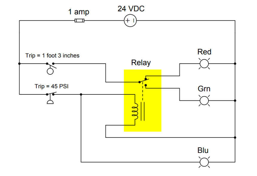
Explain Operation of the Lamp Circuit ?
Explain the operation of the circuit ? Answer : The blue lamp will be energized whenever the pressure switch senses a pressure that is less than 45 PSI. The red…

Pressure Measurement Objective Questions
Instrumentation Tools assists you with a complete guide of objective questions which mainly targets the aspirants of Electrical, Electronics and Instrumentation engineering Streams to crack the competitive exams and to…

Flow Measurement Objective Questions
Practice Flow Measurement objective questions and answers, Quiz & MCQ to crack any sort of interviews, competitive exams, and entrance tests.

Torque Measurement Objective Questions
Instrumentation Tools assists you with a complete guide of objective questions which mainly targets the aspirants of Electrical, Electronics and Instrumentation engineering Streams to crack the competitive exams and to…
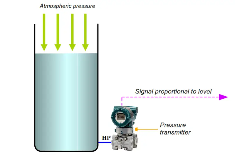
Open Tank Level Measurement using DP Transmitter
Open Tank Level Measurement using DP Transmitter The figure above illustrates an application where the level value is inferred from a pressure measurement. When the level is at the same…

Force Measurement Objective Questions
Instrumentation Tools assists you with a complete guide of objective questions which mainly targets the aspirants of Electrical, Electronics and Instrumentation engineering Streams to crack the competitive exams and to…
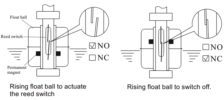
Magnetic Float Level Switch Installation Techniques
Magnetic Float Level Switch The single unit or multiple reed switch units are housed tightly in stainless steel or engineering plastic stem, and the permanent magnet is sealed into the…
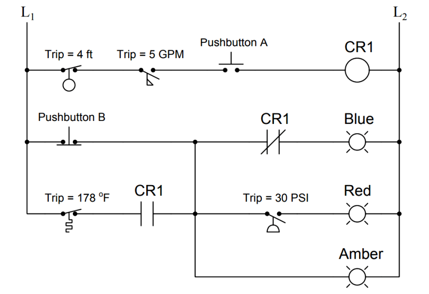
As per Process Conditions, Find out the Circuit Components Status ?
Determine the statuses of all lamps and relay coils in this circuit, given the following process conditions: Process Conditions : Flow = 7.9 GPM Pressure = 36 PSI Temperature =…
