
Count and Pack Objects from Conveyor using PLC Ladder Logic
This is a PLC Program to count and pack objects from the conveyor. Learn the PLC programming with this example problem and solution.

PLC Program to Drain Same Products from Two Tanks
This is a PLC Program to drain the same products from two tanks. Learn the PLC programming with this simple example.
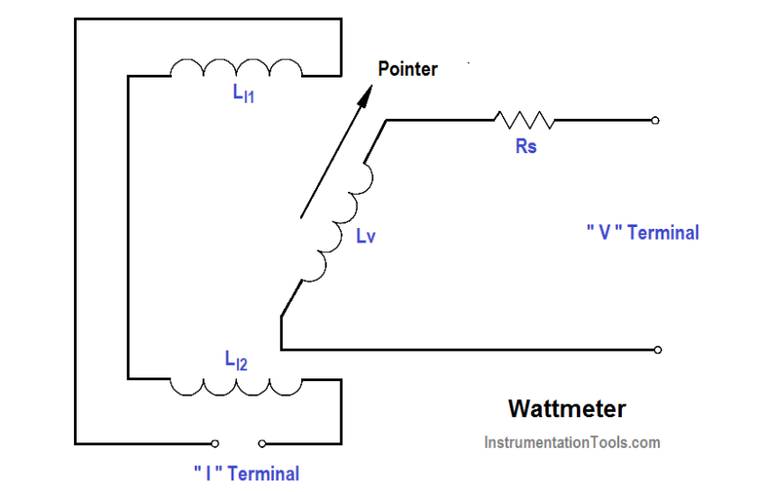
Wattmeter
The wattmeter is an instrument which measures DC power or true AC power. The wattmeter uses fixed coils to indicate current, while the movable coil indicates voltage (as shown in…
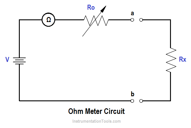
Ohm Meter
The ohm meter is an instrument used to determine resistance. A simple ohm meter (Below Figure) consists of a battery, a meter movement calibrated in ohms, and a variable resistor.…
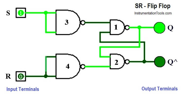
How to implement SR Flip Flop using PLC Ladder Logic
This is the PLC Program to implement SR flip flop in PLC. Learn the PLC programming with this example logic.
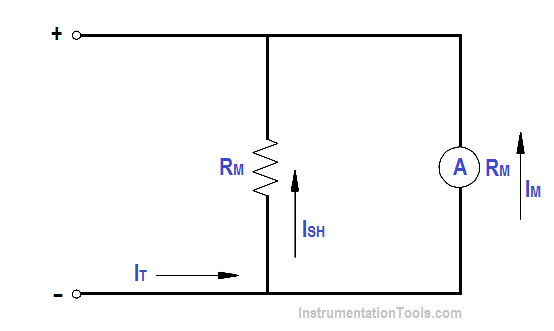
Ammeter
The ammeter measures electric current. It may be calibrated in amperes, milliamperes, or microamperes. In order to measure current, the ammeter must be placed in series with the circuit to…
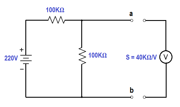
Voltmeters
A simple DC voltmeter can be constructed by placing a resistor (RS), called a multiplier, in series with the ammeter meter movement, and marking the meter face to read voltage…
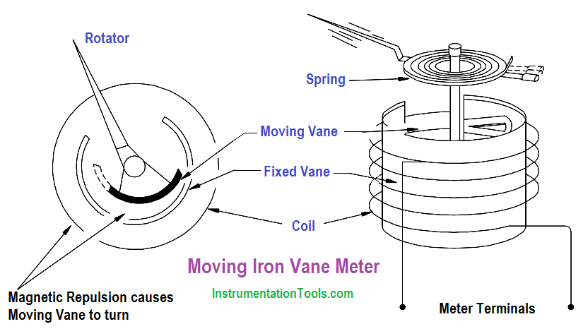
Moving Iron Vane Meter Movement
The moving iron vane movement (Figure 1) can be used to measure both AC current and voltage. By changing the meter scale calibration, the movement can be used to measure…

Electro-Dynamo Meter Movement
The electrodynamometer movement (Figure 1) has the same basic operating principle as the D’Arsonval meter movement, except that the permanent magnet is replaced by fixed coils. The moving coil and…
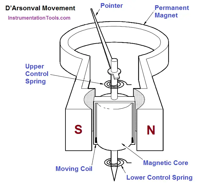
D’Arsonval Meter Movement
The most commonly used sensing mechanism used in DC ammeters, voltmeters, and ohm meters is a current-sensing device called a D’Arsonval meter movement (Figure 1). The D’Arsonval movement is a…
