Alternative to Pressure Transmitters Leg Compensation
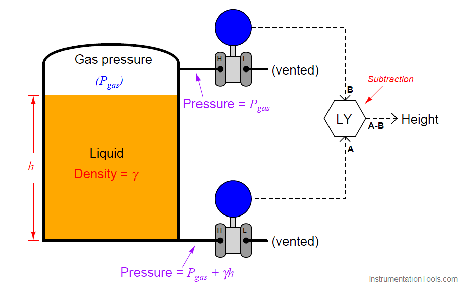
An alternative to using a compensating leg to subtract gas pressure inside an enclosed vessel is to simply use a second pressure transmitter and electronically subtract the two pressures in a computing device:

This approach enjoys the distinct advantage of avoiding a potentially wet compensating leg, but suffers the disadvantages of extra cost and greater error due to the potential calibration drift of two transmitters rather than just one. Such a system is also impractical in applications where the gas pressure is substantial compared to the hydrostatic (elevation head) pressure.
If we add a third pressure transmitter to this system, located a known distance (x) above the bottom transmitter, we have all the pieces necessary for what is called a tank expert system. These systems are used on large storage tanks operating at or near atmospheric pressure, and have the ability to measure infer liquid height, liquid density, total liquid volume, and total liquid mass stored in the tank:
The pressure difference between the bottom and middle transmitters will change only if the liquid density (Note 1 ) changes, since the two transmitters are separated by a known and fixed height difference.
Note 1 : Assuming the liquid level is equal to or greater than x. Otherwise, the pressure difference between Pbottom and Pmiddle will depend on liquid density and liquid height. However, this condition is easy to check: the level computer simply checks to see if Pmiddle and Ptop are unequal. If so, then the computer knows the liquid level exceeds x and it is safe to calculate density. If not, and Pmiddle registers the same as Ptop, the computer knows those two transmitters are both registering gas pressure only, and it knows to stop calculating density.
Algebraic manipulation shows us how the measured pressures may be used by the level computer (LY) to continuously calculate liquid density (γ):
Once the computer knows the value of γ, it may calculate the height of liquid in the tank with great accuracy based on the pressure measurements taken by the bottom and top transmitters:
With all the computing power available in the LY, it is possible to characterize the tank such that this height measurement converts to a precise volume measurement (V ), which may then be converted into a total mass (m) measurement based on the mass density of the liquid (ρ) and the acceleration of gravity (g). First, the computer calculates mass density based on the proportionality between mass and weight (shown here starting with the equivalence between the two forms of the hydrostatic pressure formula):
ρgh = γh
ρg = γ
ρ = γ/g
Armed with the mass density of the liquid inside the tank, the computer may now calculate total liquid mass stored inside the tank:
m = ρV
Dimensional analysis shows how units of mass density and volume cancel to yield only units of mass in this last equation:
[kg] = [ kg/m3 ] m3
Here we see a vivid example of how several measurements may be inferred from just a few actual process (in this case, pressure) measurements. Three pressure measurements on this tank allow us to compute four inferred variables: liquid density, liquid height, liquid volume, and liquid mass.
The accurate measurement of liquids in storage tanks is not just useful for process operations, but also for conducting business. Whether the liquid represents raw material purchased from a supplier, or a processed product ready to be pumped out to a customer, both parties have a vested interest in knowing the exact quantity of liquid bought or sold.
Measurement applications such as this are known as custody transfer, because they represent the transfer of custody (ownership) of a substance exchanged in a business agreement. In some instances, both buyer and seller operate and maintain their own custody transfer instrumentation, while in other instances there is only one instrument, the calibration of which validated by a neutral party.
A photograph showing the two lower pressure transmitters of a tank expert system on a refrigerated butane storage vessel appears here:
The upper and lower instruments are pressure transmitters, while the middle instrument is a temperature sensor used to report the temperature of the refrigerated butane to the control system.
Credits : Tony R. Kuphaldt – Creative Commons Attribution 4.0 License
In this post, we will learn the basic requirements for a network switch to be…
The PLC panel and MCC panel interface signals are start, stop, run feedback, trip, local…
In this article, we are going to discuss about shutter door control using induction motor…
Electrical Drives control the motion of electric motors. Motion control is required in industrial and…
PLC ladder logic design to control 3 motors with toggle switch and explain the program…
VFD simulator download: Master the online tool from the Yaskawa V1000 & programming software for…
View Comments
Most excellent article, very well written, showing great methods.