AC generators are widely used to produce AC voltage. To understand how these generators operate, the basic theory of operation must first be understood.
A simple AC generator consists of:
(a) a strong magnetic field,
(b) conductors that rotate through that magnetic field, and
(c) a means by which a continuous connection is provided to the conductors as they are rotating (Figure 3).
The strong magnetic field is produced by a current flow through the field coil of the rotor. The field coil in the rotor receives excitation through the use of slip rings and brushes. Two brushes are spring-held in contact with the slip rings to provide the continuous connection between the field coil and the external excitation circuit.
The armature is contained within the windings of the stator and is connected to the output. Each time the rotor makes one complete revolution, one complete cycle of AC is developed. A generator has many turns of wire wound into the slots of the rotor.
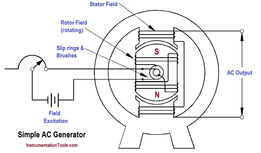
Figure 3 : Simple AC Generator
The magnitude of AC voltage generated by an AC generator is dependent on the field strength and speed of the rotor. Most generators are operated at a constant speed; therefore, the generated voltage depends on field excitation, or strength.
The frequency of the generated voltage is dependent on the number of field poles and the speed at which the generator is operated, as indicated in below Equation.
where
f = frequency (Hz)
P = total number of poles
N = rotor speed (rpm)
120 = conversion from minutes to seconds and from poles to pole pairs
The 120 in above Equation is derived by multiplying the following conversion factors.
In this manner, the units of frequency (hertz or cycles/sec.) are derived.
Electrical Drives control the motion of electric motors. Motion control is required in industrial and…
PLC ladder logic design to control 3 motors with toggle switch and explain the program…
VFD simulator download: Master the online tool from the Yaskawa V1000 & programming software for…
The conveyor sorting machine is widely used in the packing industries using the PLC program…
Learn the example of flip-flop PLC program for lamps application using the ladder logic to…
In this article, you will learn the STAR DELTA programming using PLC controller to start…


