This article will discuss the paint mixing process using the XG5000 PLC program. This PLC program is designed to control the paint mixing process with the correct proportion of materials. The system ensures that components such as pigments, solvents, and binders are automatically mixed in predetermined measurements based on time. Additionally, the program will count the mixing processes that have been carried out.
Program Objective
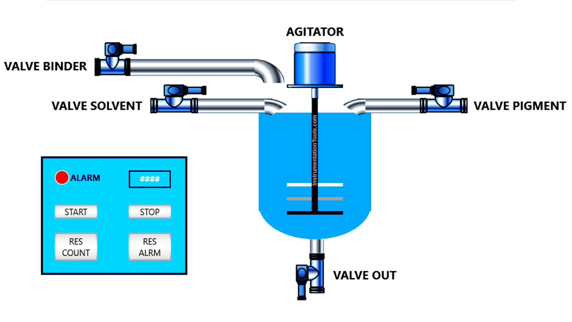
Here are the steps of the control logic:
The PLC system will only operate when the Start button is pressed.
- Step 1: Filling Material A (Pigment) for 5 seconds.
- Step 2: Filling Material B (Solvent) for 7 seconds.
- Step 3: Filling Material C (Binder) for 4 seconds.
- Step 4: Mixing the materials for 10 seconds.
- Step 5: Emptying the tank. This can only be done manually using a button.
The process is complete, and the Process Completion Indicator Light turns ON.
The system counts the number of processes performed.
The Indicator Light will turn OFF if the Reset button is pressed.
Mapping Details
| S.No. | Comment | Input (I) | Output (Q) | Timers | Memory Words | Memory Bit |
|---|---|---|---|---|---|---|
| 1 | PB_START | P0000 | ||||
| 2 | PB_STOP | P0001 | ||||
| 3 | PB_VALVE_OUT | P0002 | ||||
| 4 | RESET_ALARM | P0003 | ||||
| 5 | RESET_COUNT_PROCESS | P0004 | ||||
| 6 | VALVE_PIGMENT | P0040 | ||||
| 7 | VALVE_SOLVENT | P0041 | ||||
| 8 | VALVE_BINDER | P0042 | ||||
| 9 | MIXER_AGITATOR | P0043 | ||||
| 10 | LAMP_ALARM | P0044 | ||||
| 11 | VALVE_OUT | P0045 | ||||
| 12 | TIMER_PIGMENT | T000 | ||||
| 13 | TIMER_SOLVENT | T001 | ||||
| 14 | TIMER_BINDER | T002 | ||||
| 15 | TIMER_AGITATOR | T003 | ||||
| 16 | COUNT_PROCESS | M000 | ||||
| 17 | SYSTEM_ON | M1000 |
XG5000 PLC Program for Paint Mixing Process
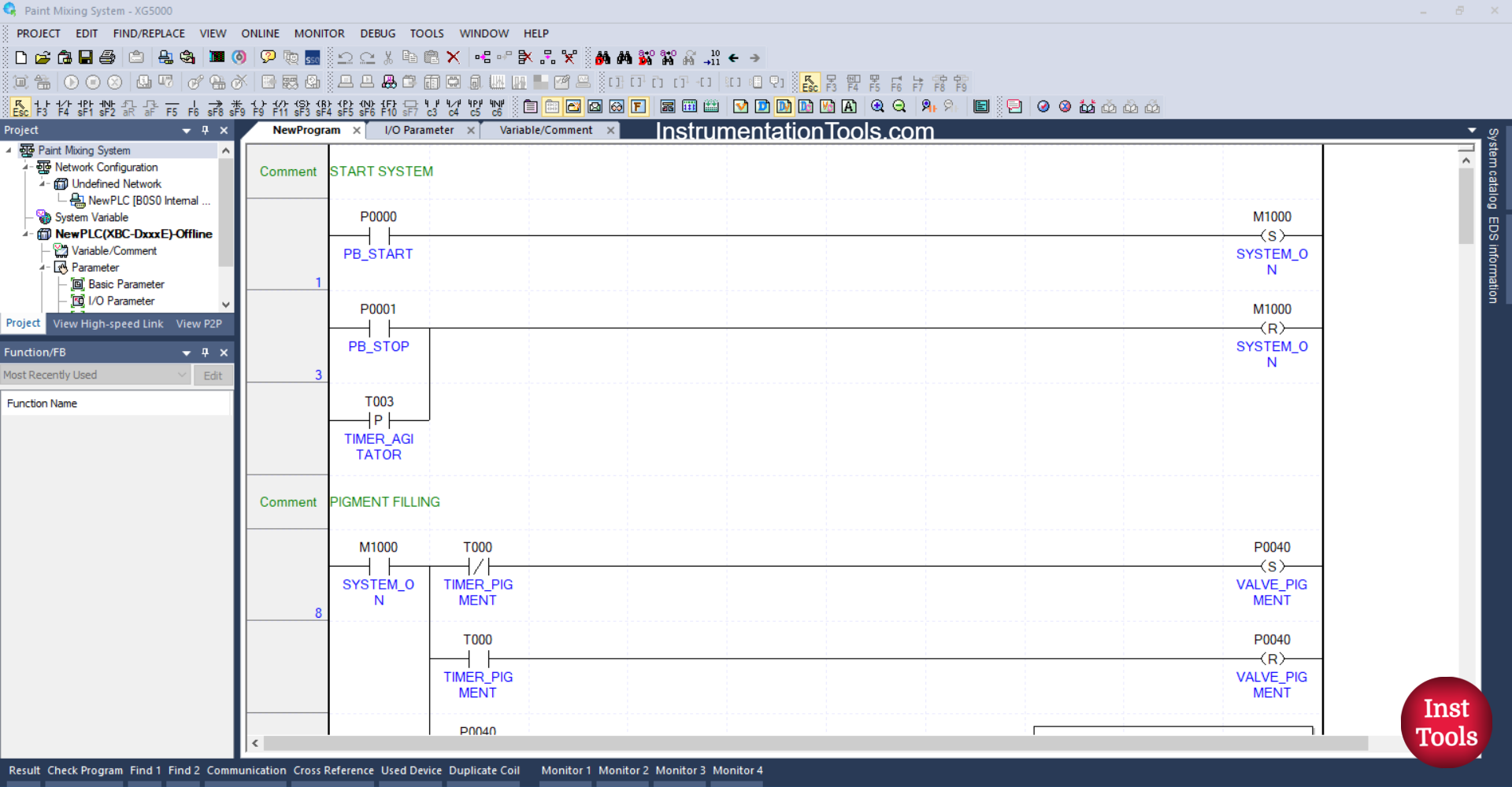
RUNG 1 (START SYSTEM)
In this rung, if the PB_START (P0000) button is pressed, the memory bit SYSTEM_ON (M1000) will be in the HIGH state. Because it uses the SET Coil instruction, the memory bit SYSTEM_ON (M1000) will remain in the HIGH state even though the PB_START (P0000) button has been released.
RUNG 3
The memory bit SYSTEM_ON (M1000) will return to the LOW state if the PB_STOP (P0001) button has been pressed or the NO contact of the TIMER_AGITATOR (T003) timer is in the HIGH state. Because it uses the RESET Coil instruction.
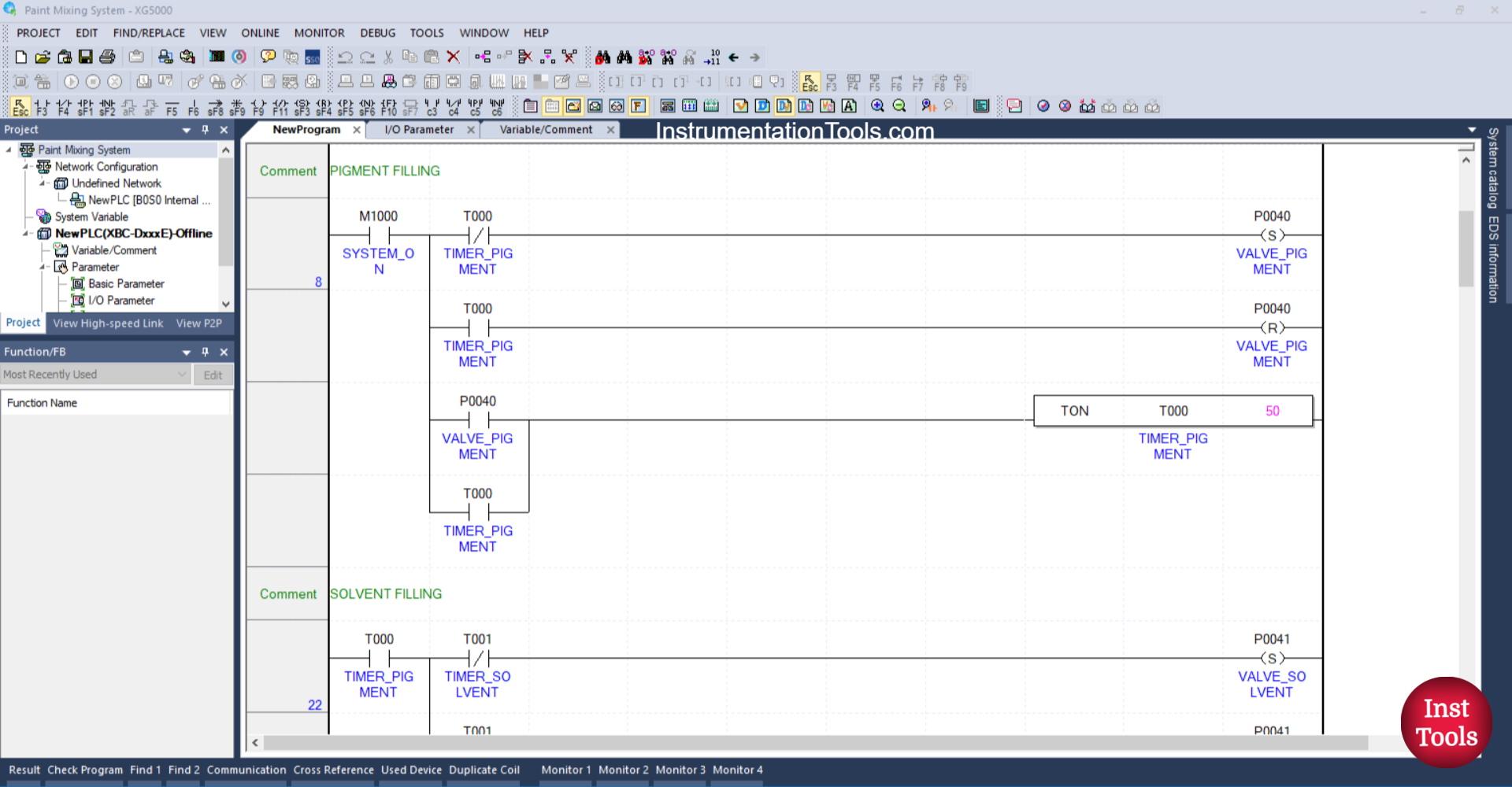
RUNG 8 (PIGMENT FILLING)
In this rung, the output VALVE_PIGMENT (P0040) will OPEN when the NO contact of the memory bit SYSTEM_ON (M1000) is in a HIGH state. The timer TIMER_PIGMENT (T000) will start counting up to 5 seconds when the NO contact of VALVE_PIGMENT (P0040) is in a HIGH state.
After TIMER_PIGMENT (T000) completes counting, the output VALVE_PIGMENT (P0040) will CLOSE because the RESET Coil instruction of VALVE_PIGMENT (P0040) is triggered by the NO contact of TIMER_PIGMENT (T000) and due to the Interlock from TIMER_PIGMENT (T000) on the SET Coil instruction of VALVE_PIGMENT (P0040).
The timer TIMER_PIGMENT (T000) will remain ON because it uses Latching.
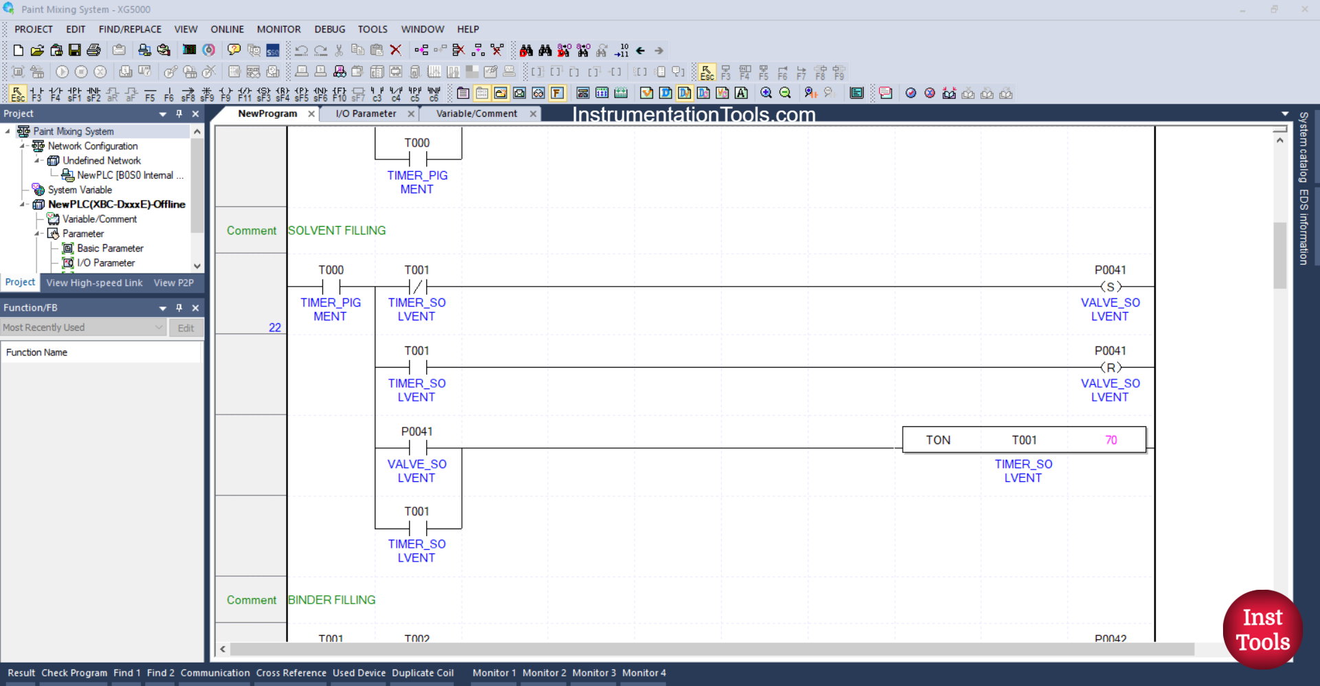
RUNG 22 (SOLVENT FILLING)
In this rung, the output VALVE_SOLVENT (P0041) will OPEN when the NO contact of the timer TIMER_PIGMENT (T000) is in the HIGH state. The timer TIMER_SOLVENT (T001) will start counting for 7 seconds when the NO contact of VALVE_SOLVENT (P0041) is in the HIGH state.
After the timer TIMER_SOLVENT (T001) finishes counting, the output VALVE_SOLVENT (P0041) will CLOSE because the RESET Coil instruction for the output VALVE_SOLVENT (P0041) is triggered by the NO contact of the timer TIMER_SOLVENT (T001) and due to the interlock from the timer TIMER_SOLVENT (T001) on the SET Coil instruction for the output VALVE_SOLVENT (P0041).
The timer TIMER_SOLVENT (T001) will remain ON because it uses Latching.
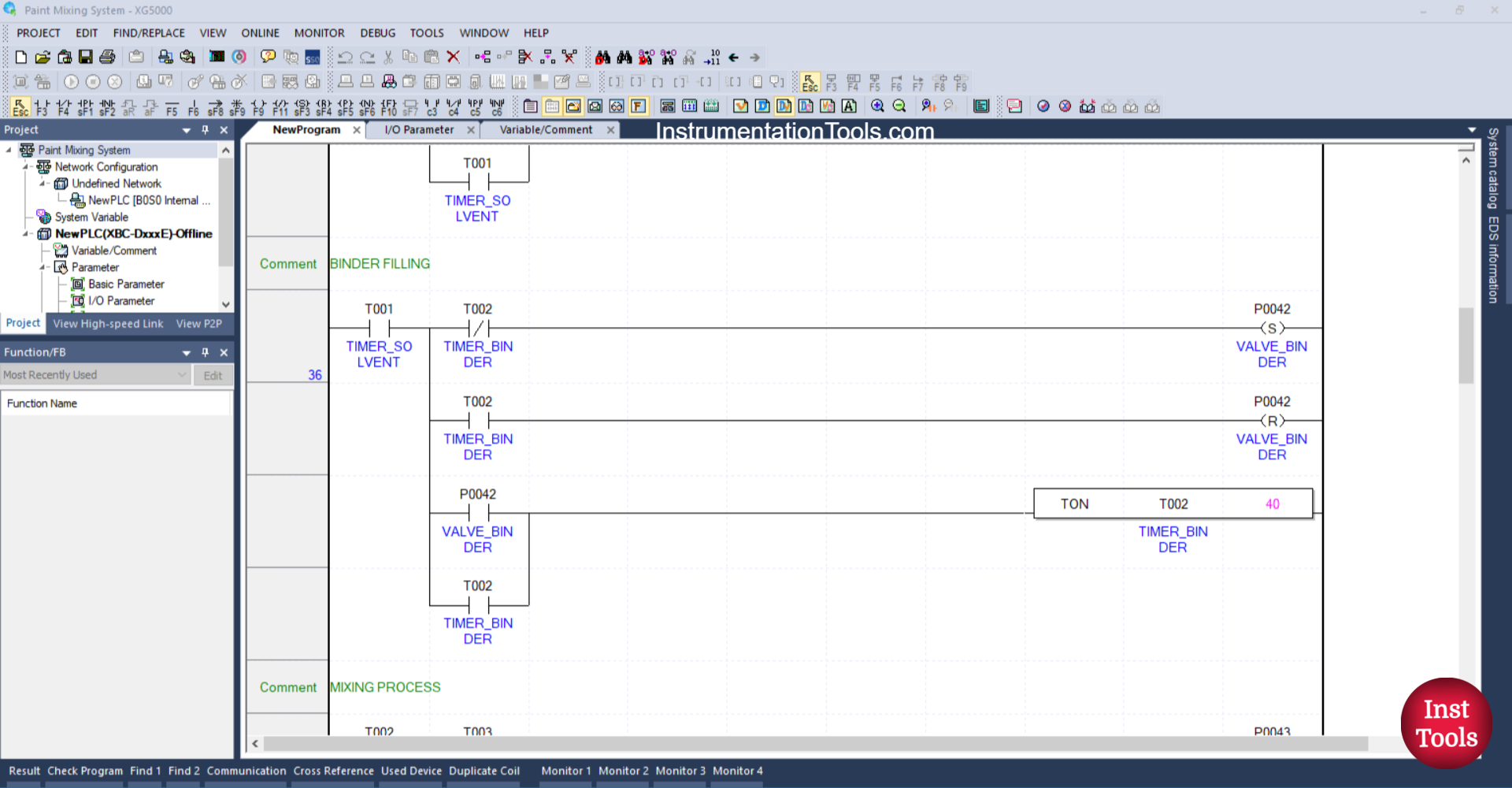
RUNG 36 (BINDER FILLING)
In this rung, the output VALVE_BINDER (P0042) will OPEN when the NO contact of the timer TIMER_SOLVENT (T001) is in the HIGH state. The timer TIMER_BINDER (T002) will start counting for 4 seconds when the NO contact of VALVE_BINDER (P0042) is in the HIGH state.
After the timer TIMER_BINDER (T002) finishes counting, the output VALVE_BINDER (P0042) will CLOSE because the RESET Coil instruction for the output VALVE_BINDER (P0042) is triggered by the NO contact of the timer TIMER_BINDER (T002) and due to the interlock from the timer TIMER_BINDER (T002) on the SET Coil instruction for the output VALVE_BINDER (P0042).
The timer TIMER_BINDER (T002) will remain ON because it uses a Latching.
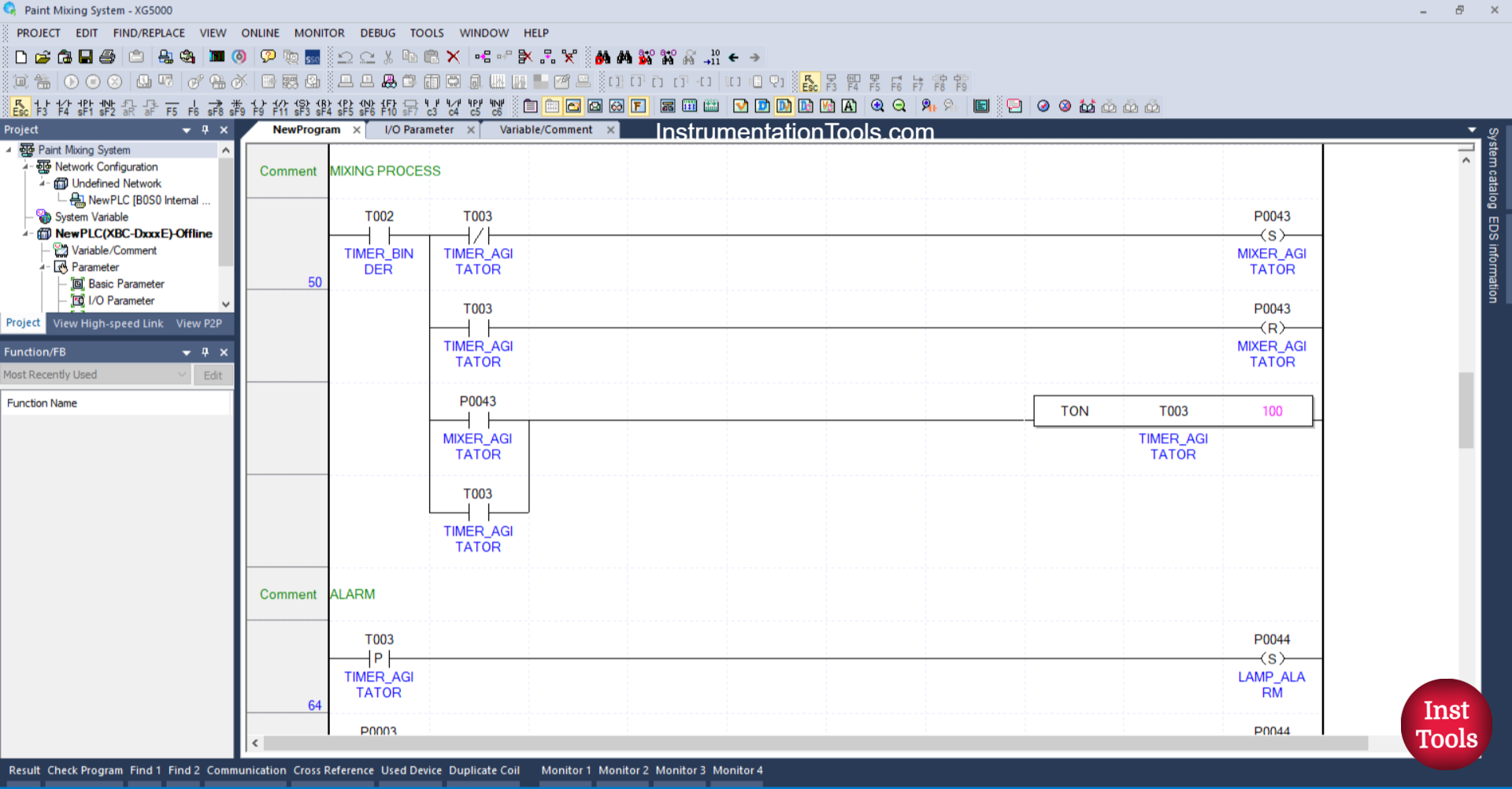
RUNG 50 (MIXING PROCESS)
In this rung, the output MIXER_AGITATOR (P0043) will turn ON when the NO contact of the timer TIMER_BINDER (T002) is in a HIGH state. The timer TIMER_AGITATOR (T003) will start counting for 10 seconds when the NO contact of MIXER_AGITATOR (P0043) is in a HIGH state.
After the timer TIMER_AGITATOR (T003) finishes counting, the output MIXER_AGITATOR (P0043) will turn OFF because the RESET Coil instruction for the output MIXER_AGITATOR (P0043) is triggered by the NO contact of the timer TIMER_AGITATOR (T003) and due to the interlock from the timer TIMER_AGITATOR (T003) on the SET Coil instruction of the output MIXER_AGITATOR (P0043).
The timer TIMER_AGITATOR (T003) will remain ON because it uses a Latching.
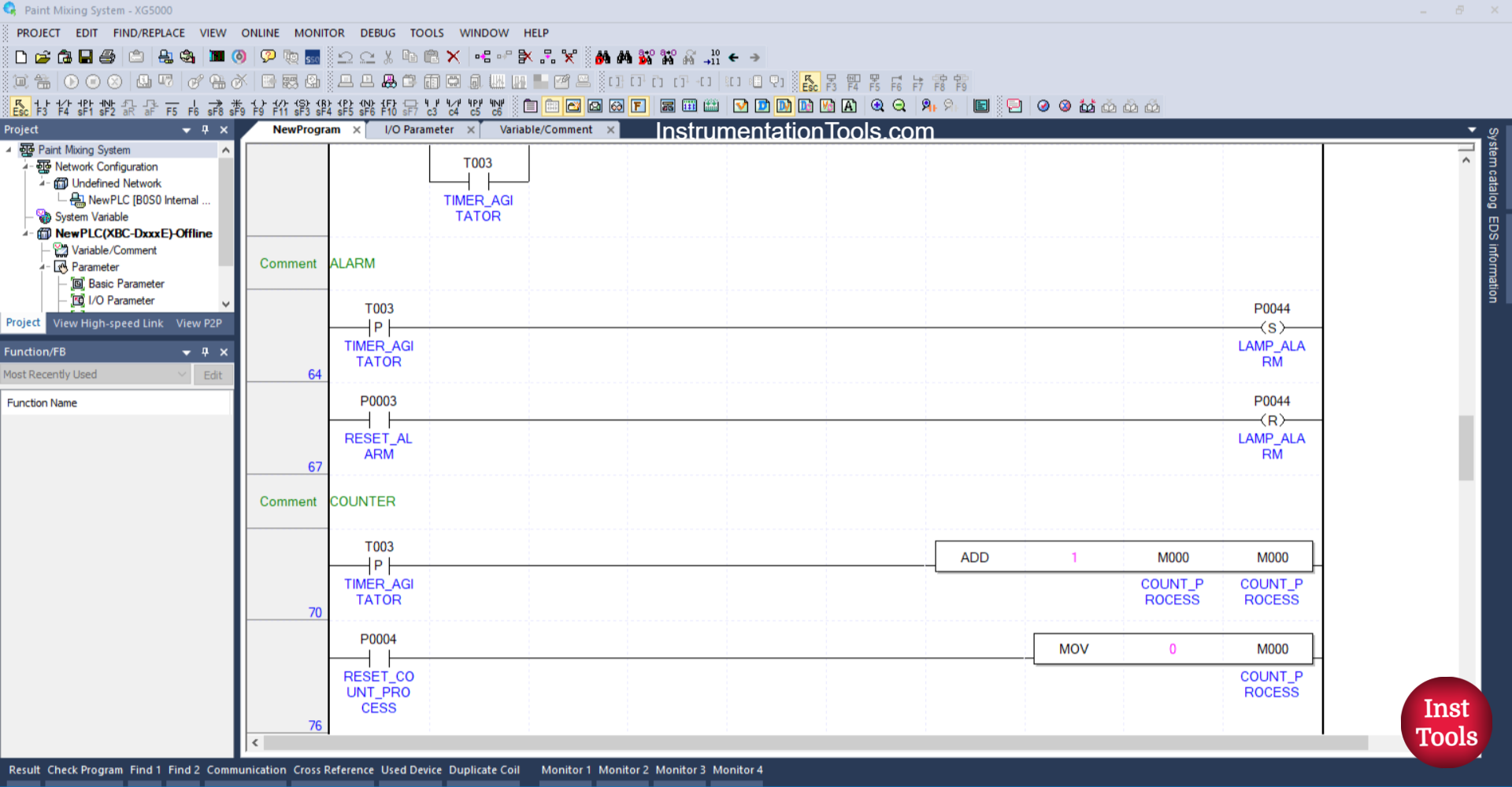
RUNG 64 (ALARM)
In this Rung, the LAMP_ALARM (P0044) output will be ON when the NO contact of the TIMER_ AGITATOR (T003) timer is in the HIGH state. The LAMP_ALARM (P0044) output will remain ON even though the NO contact of the TIMER_ AGITATOR (T003) timer is in the LOW state, because it uses the SET Coil instruction.
RUNG 67
In this Rung, the LAMP_ALARM (P0044) output will be OFF when the RESET_ALARM (P0003) button is pressed. Because it uses the RESET Coil instruction.
RUNG 70 (COUNTER)
In this rung, the value in the memory word COUNT_PROCESS (M000) will increase (+1) when the NO contact of the TIMER_ AGITATOR (T003) timer is in the HIGH state. Because it uses the ADD instruction.
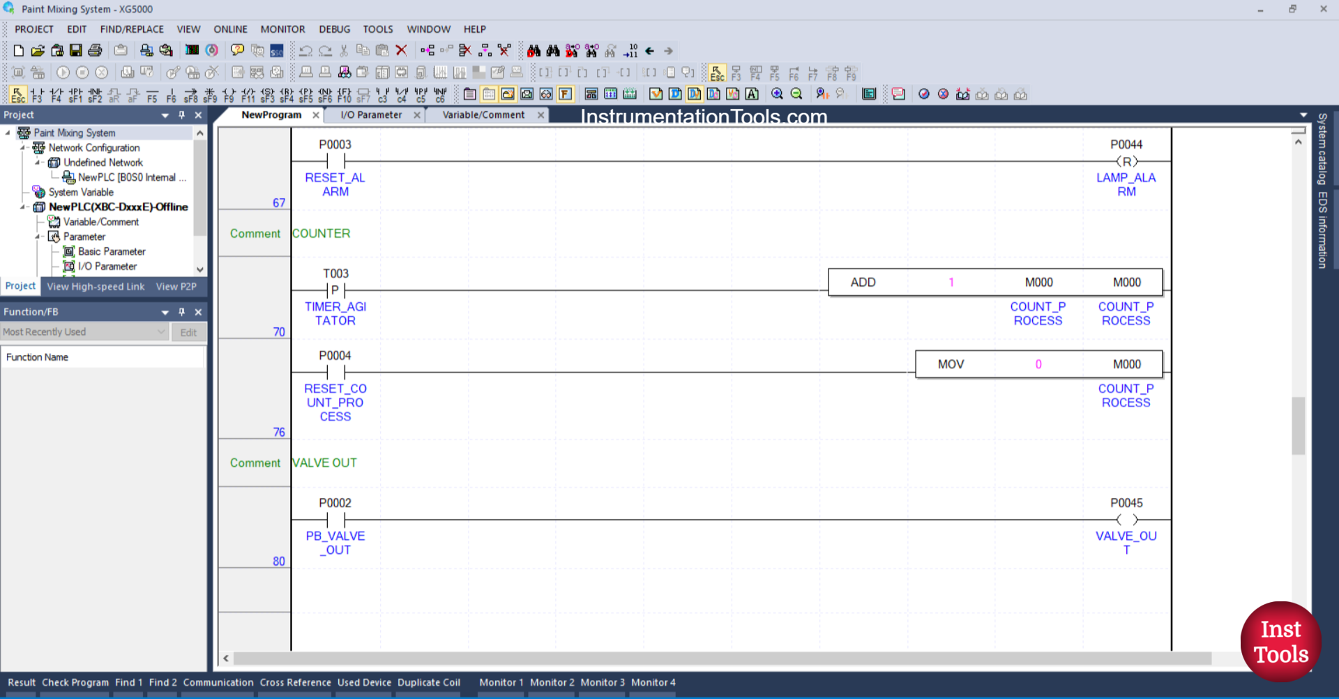
RUNG 76
In this rung, the value in the memory word COUNT_PROCESS (M000) will be reset to zero “0” when the RESET_COUNT_PROCESS (P0004) button is pressed. Because it uses the MOV instruction.
RUNG 76
In this Rung, the VALVE_OUT (P0045) output will OPEN when the PB_VALVE_OUT (P0002) button is pressed.
Read Next:
- Cargo Elevator System Using PLC Programming
- Object Detection Based Door Opening PLC System
- Auto Manual Sequential Lamps using XGB Program
- Water Fountain Control PLC Exercises and Solutions
- Tia Portal – Optimized and Standard Data Block Access