This article will discuss the Elevator Control System with Up/Down logic using Omron PLC CX-Programmer software. The elevator system is designed to operate only when the elevator door is closed. The elevator can be operated manually to move up and down using buttons. When operated in auto mode, the elevator can only move up or down by one floor at a time. Each floor has a button to move to another floor.
Program Objective
System Sequence
The elevator can only operate when the door is fully closed.
Manual Mode: The elevator can move up or down by pressing the UP or DOWN button.
Auto Mode: In Auto Mode, the elevator will move automatically to the selected floor.
Floor 1:
- Initial Condition: Elevator is at Floor 1.
- Input: The “Up” button is pressed.
- Process: The elevator activates the motor to move upward.
- Output: The elevator stops at Floor 2.
Floor 2:
- Initial Condition: Elevator is at Floor 2.
- Input: The “Up” OR “Down” button is pressed.
- Process: The elevator activates the motor based on the input, moving upward or downward.
- Output: The elevator stops at the desired floor.
Floor 3:
- Initial Condition: Elevator is at Floor 3.
- Input: The “Down” button is pressed.
- Process: The elevator activates the motor to move downward.
- Output: The elevator stops at Floor 2.
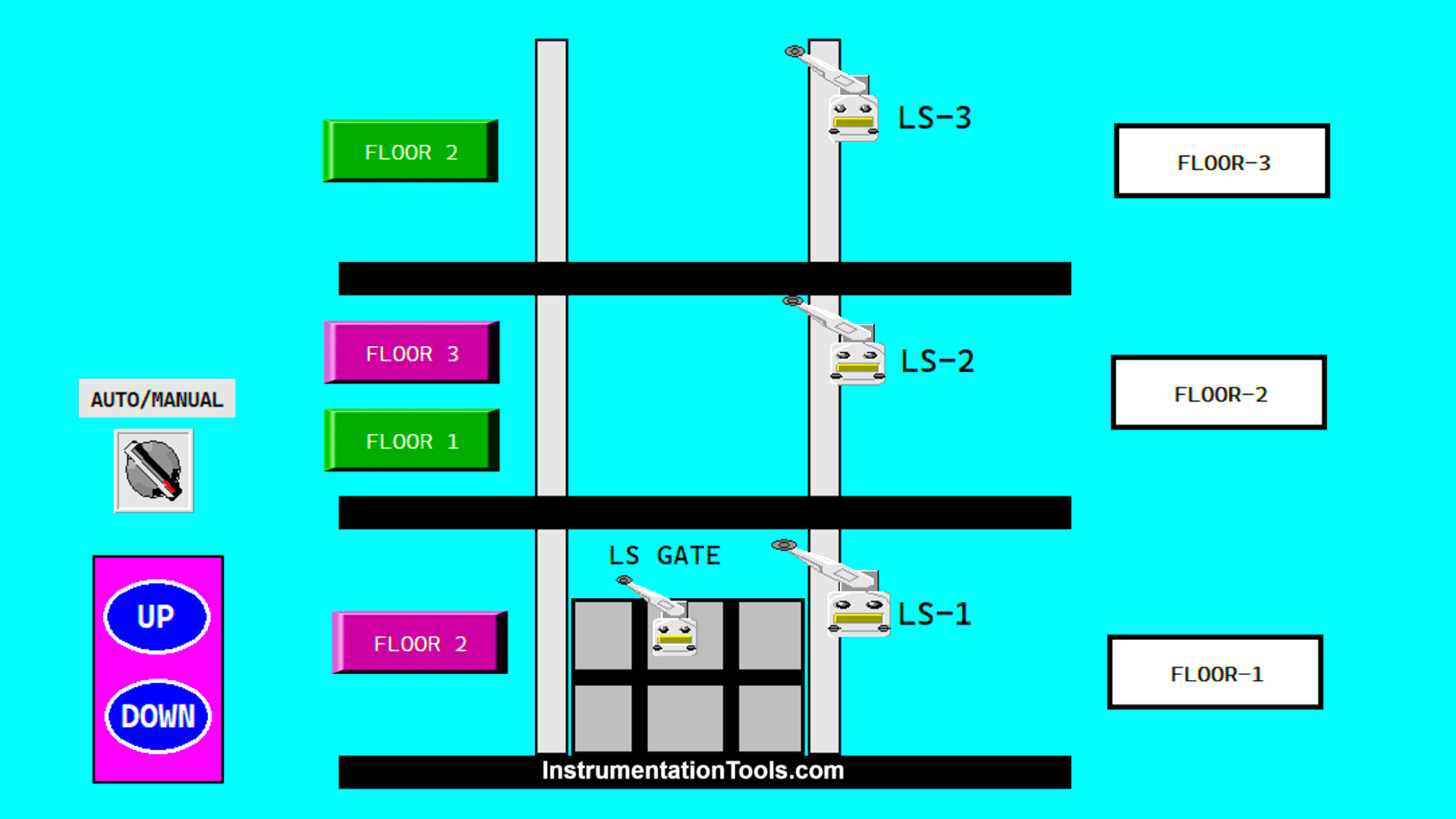
Each floor has a Limit switch. The Limit switch will signal the Elevator to stop on the right Floor.
Elevator System
IO Mapping
| S.No. | Comment | Input (I) | Output (Q) | Memory Bit |
|---|---|---|---|---|
| 1 | PB_START | 0.00 | ||
| 2 | PB_STOP | 0.01 | ||
| 3 | AUTO/MANUAL | 0.02 | ||
| 4 | PB_UP_MANUAL | 0.03 | ||
| 5 | PB_DOWN_MANUAL | 0.04 | ||
| 6 | LS_GATE | 0.05 | ||
| 7 | UP_FLOOR2 | 0.06 | ||
| 8 | LS_FLOOR1 | 0.07 | ||
| 9 | LS_FLOOR2 | 1.00 | ||
| 10 | UP_FLOOR3 | 1.01 | ||
| 11 | LS_FLOOR3 | 1.02 | ||
| 12 | DOWN_FLOOR1 | 1.03 | ||
| 13 | DOWN_FLOOR2 | 1.04 | ||
| 14 | OUT_UP | 100.00 | ||
| 15 | OUT_DOWN | 100.01 | ||
| 16 | FLOOR1_TO_2 | 100.02 | ||
| 17 | FLOOR2_TO_3 | 100.03 | ||
| 18 | FLOOR2_TO_1 | 100.04 | ||
| 19 | FLOOR3_TO_2 | 100.05 | ||
| 20 | SYSTEM_ON | W0.00 |
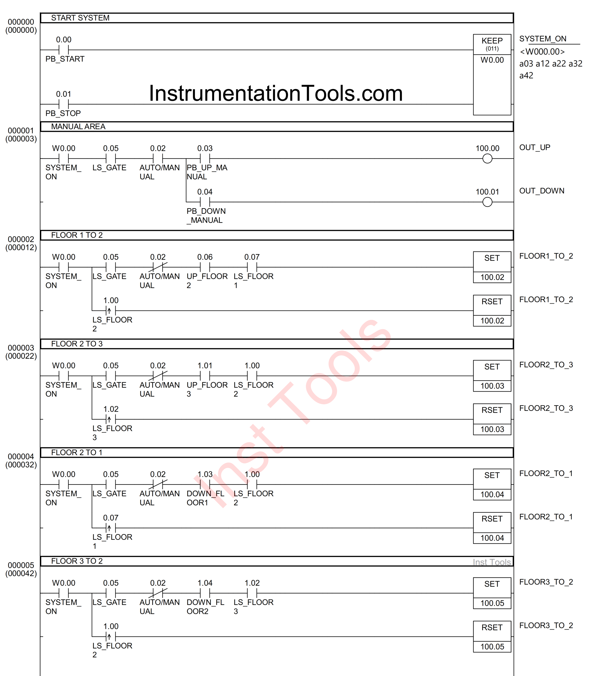
Omron PLC Elevator Control
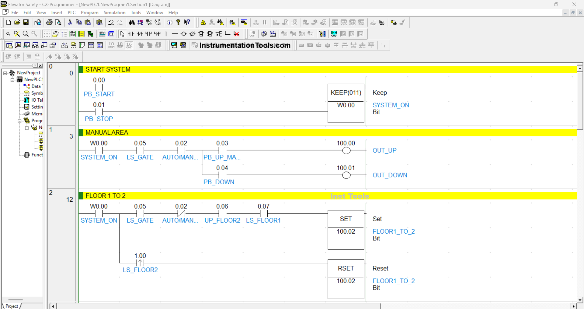
RUNG 0 (START SYSTEM)
In this Rung, the memory bit SYSTEM_ON (W0.00) will be in the HIGH state when the PB_START (0.00) button is pressed. Because it uses the KEEP(011) instruction, the memory bit SYSTEM_ON (W0.00) will remain in the HIGH state even though the PB_START (0.00) button has been released.
The memory bit SYSTEM_ON (W0.00) will be in the LOW state if the PB_STOP (0.01) button is pressed.
RUNG 1 (MANUAL AREA)
In this Rung, the Output OUT_UP (100.00) will be ON if the NO contact of the memory bit SYSTEM_ON (W0.00), Limit Switch LS_GATE (0.05), Selector Switch AUTO/MANUAL (0.02) are in the HIGH state, and the PB_UP_MANUAL (0.03) button is pressed.
The OUT_DOWN (100.01) output will be ON if the NO contact of the memory bit SYSTEM_ON (W0.00), Limit Switch LS_GATE (0.05), Selector Switch AUTO/MANUAL (0.02) are in the HIGH state, and the PB_DOWN_MANUAL (0.04) button is pressed.
RUNG 2 (FLOOR 1 to 2)
In this Rung, when the NO contact of the memory bit SYSTEM_ON (W0.00), Limit Switch LS_GATE (0.05), LS_FLOOR1 (0.07) are in the HIGH state, and the UP_FLOOR2 (0.06) button is pressed, the output FLOOR1_TO_2 (100.02) will be ON.
Even though the UP_FLOOR2 (0.06) button has been released and the Limit Switch LS_FLOOR1 (0.07) is in the LOW state, the output state of FLOOR1_TO_2 (100.02) will remain in the ON state because it uses the SET Instruction.
Because it uses the RSET Instruction, the output FLOOR1_TO_2 (100.02) will be OFF if the NO contact of the Limit Switch LS_FLOOR2 (1.00) is in the HIGH state.
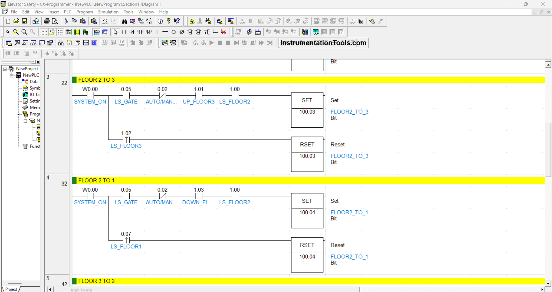
RUNG 3 (FLOOR 2 to 3)
In this Rung, when the NO contact of the memory bit SYSTEM_ON (W0.00), Limit Switch LS_GATE (0.05), LS_FLOOR2 (1.00) are in the HIGH state, and the UP_FLOOR3 (1.01) button is pressed, the FLOOR2_TO_3 (100.03) output will be ON.
Even though the UP_FLOOR3 (1.01) button has been released and the Limit Switch LS_FLOOR2 (1.00) is in the LOW state, the output state of FLOOR2_TO_3 (100.03) will remain in the ON state because it uses the SET Instruction.
Because it uses the RSET Instruction, the output FLOOR2_TO_3 (100.03) will be OFF if the NO contact of the Limit Switch LS_FLOOR3 (1.02) is in the HIGH state.
RUNG 4 (FLOOR 2 to 1)
In this Rung, when the NO contact of the memory bit SYSTEM_ON (W0.00), Limit Switch LS_GATE (0.05), LS_FLOOR2 (1.00) are in the HIGH state and the DOWN_FLOOR1 (1.03) button is pressed, the output FLOOR2_TO_1 (100.04) will be ON.
Even though the DOWN_FLOOR1 (1.03) button has been released and the Limit Switch LS_FLOOR2 (1.00) is in the LOW state, the output state of FLOOR2_TO_1 (100.04) will remain in the ON state because it uses the SET instruction.
Because it uses the RSET Instruction, the output FLOOR2_TO_1 (100.04) will be OFF if the NO contact of the Limit Switch LS_FLOOR1 (0.07) is in the HIGH state.

RUNG 5 (FLOOR 3 to 2)
In this Rung, when the NO contact of the memory bit SYSTEM_ON (W0.00), Limit Switch LS_GATE (0.05), and LS_FLOOR2 (1.00) are in the HIGH state, and the DOWN_FLOOR2 (1.04) button is pressed, the output FLOOR3_TO_2 (100.05) will be ON.
Even though the DOWN_FLOOR2 (1.04) button has been released and the Limit Switch LS_FLOOR3 (1.02) is in the LOW state, the output state of FLOOR3_TO_2 (100.05) will remain in the ON state because it uses the SET instruction.
Because it uses the RSET Instruction, the output FLOOR3_TO_2 (100.05) will be OFF if the NO contact of the Limit Switch LS_FLOOR2 (1.00) is in the HIGH state.
Read Next:
- Latching and Interlocking Pump Control in PLC Logic
- Siemens PLC Logic for Bottle Weight Verification
- XG5000 PLC Project: Continuous Liquid Tank Logic
- PLC Example: Water Level-Based Pump Control
- Turn ON Lamps Alternately for Set Cycles in PLC