Inst ToolsInst ToolsInst Tools
  • Courses
  • Videos
  • Q & A
    • Interview
      • Instrumentation
      • Electronics
      • Electrical
      • Practical Questions
    • MCQ
      • Instrumentation MCQ
      • Electrical MCQ
      • Electronics MCQ
      • Control Systems MCQ
      • Analog Electronics MCQ
      • Digital Electronics MCQ
      • Power Electronics MCQ
      • Microprocessor MCQ
      • Multiple Choice Questions
  • EE
    • Electronics
      • Electronics Q & A
      • Electronic Basics
      • Electronic Devices & Circuits
      • Electronics Animation
      • Digital Electronics
    • Electrical
      • Electrical Basics
      • Electrical Q & A
      • Power Electronics
      • Electrical Machines
      • Electrical Animation
      • Power Systems
      • Switchgear & Protection
      • Transmission & Distribution
  • Measure
    • Control Valves
    • Calibration
    • Temperature
    • Pressure
    • Flow
    • Level
    • Analyzers
    • Switches
    • Vibration
    • Solenoid Valve
  • Control
    • PLC Tutorials
    • Control Systems
    • Safety Instrumented System (SIS)
    • Communication
    • Fire & Gas System
  • More
    • Design
    • Tools
    • Animation
    • Basics
    • Formulas
    • Standards
    • TextBooks
    • Common
    • Software
    • Excel Tools
    • Erection & Commissioning
    • Process Fundamentals
    • Videos
    • Books
Search
All rights reserved. Reproduction in whole or in part without written permission is prohibited.
Reading: Purging of Instruments
Share
Notification Show More
Font ResizerAa
Inst ToolsInst Tools
Font ResizerAa
  • Courses
  • PLC Tutorials
  • Control Systems
Search
  • Courses
  • Videos
  • Q & A
    • Interview
    • MCQ
  • EE
    • Electronics
    • Electrical
  • Measure
    • Control Valves
    • Calibration
    • Temperature
    • Pressure
    • Flow
    • Level
    • Analyzers
    • Switches
    • Vibration
    • Solenoid Valve
  • Control
    • PLC Tutorials
    • Control Systems
    • Safety Instrumented System (SIS)
    • Communication
    • Fire & Gas System
  • More
    • Design
    • Tools
    • Animation
    • Basics
    • Formulas
    • Standards
    • TextBooks
    • Common
    • Software
    • Excel Tools
    • Erection & Commissioning
    • Process Fundamentals
    • Videos
    • Books
Follow US
All rights reserved. Reproduction in whole or in part without written permission is prohibited.
Inst Tools > Blog > Standards > Purging of Instruments

Purging of Instruments

Last updated: July 3, 2020 8:41 pm
Editorial Staff
Standards
No Comments
Share
6 Min Read
SHARE

Here we shall see recommended practices for the protection of the instrument from harsh process conditions. In this article, we shall learn about the purging methods to protect the instrument.

Contents
Purging of InstrumentsPurge FluidsTypical Purging InstallationRead Next:

Purging of Instruments

Although purges are difficult to maintain, some process measurements are made possible only by the use of purging.

Purge fluids are introduced into the instrument impulse lines, manifold valves, or the instrument itself and flow out through the process connections.

The purge fluid serves to seal the instrument and sweep the lines clean of the process material. The purge fluid must be compatible with the process stream.

Purge systems are commonly used on solids bearing streams, streams subject to coking or solidification, and streams carrying corrosives or other contaminants that might damage the instrument or its connections. For solids bearing streams, the purge instrument connections to the process should be vertically up or angled up.

The addition of purge fluid close to the measurement connections minimizes pressure drop due to the flow rate of the purging fluid.

In some instances, it is advisable to inject the purge fluid at the instrument, but this type of installation requires particular care in the design of the impulse piping and establishment of the purge flow rate to avoid measurement error.

Purge systems do not always eliminate the need for heating. Certain viscous streams require heat tracing not only for the instrument and its connections but also for the line supplying the purge fluid.

Purge Fluids

Purging of instrument lines requires a suitable purge fluid (liquid or gas) at a pressure higher than the maximum process pressure possible at the point of measurement. This ensures continuous flow into the process connection.

The purge fluid should be clean, free from solids, and compatible with and non-contaminating to the process. The temperature of the purge fluid should not cause a change of state (flashing, condensation, or solidification) of the process or purge fluid.

The reliability of the source of supply is an important consideration. A source independent of the process is preferable so that it is available even when the process is not operating normally.

To be effective the purge fluid must be fed to the system continuously at a controlled rate. Restriction orifices, purge meters, or at high pressure, plunger pumps are used to determine and limit flow. Where the pressure at the point of measurement varies appreciably, a differential-pressure regulator should be used in conjunction with a restriction orifice or a purge meter to ensure a constant purge.

Too many factors are involved to attempt to set high flow limits. If errors exist as a result of excessive purge flow rate, errors can be detected by momentarily stopping the purge flow and observing the transmitter output.

Care should be exercised in calculating purge rates to orifice flanges because the orifice tap is bottom drilled to ¼, 3/8, or ½ inch. The ¼ inch orifice drilling may prove restrictive for the higher purge rate. For gases, typical purge velocities range from 5 to 50 inches per second (2 to 20 centimeters per second).

For liquids, typical purge velocities range from 0.1 to 4 inches per second (0.4 to 1.6 centimeters per second). The flow rate to each tap on an orifice meter installation should be the same. The purge rotameter is the most convenient device for determining and establishing purge flow.

The purge rotameter is the most convenient device for determining and establishing purge flow.

Note: Glass-tube rotameters should not be used for hydrocarbons or hazardous chemicals.

A standard purge rotameter with a range of 0.38-3.8 gallons per hour (1.4-14.0 liters per hour) of water or 0.2-2.0 actual cubic feet per hour (6.0-60.0 liters per hour) of air is normally satisfactory for purging clean fluids; however, where the process fluids tend to clog or deposit sediment, the rate should be increased.

Properly sized and installed restriction orifices provide reliable service when the pressure across them is properly regulated. The flow rate of liquids or gases through such orifices can be calculated by formulas found in flow metering, mechanical engineering, and similar handbooks. The calculated orifice sizes are normally rounded to the nearest standard drill size.

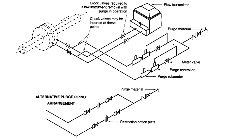
Typical Purging Installation

Below we can see typical purging installation.

Typical Purging Installation

Interest to add any further points? Share with us through below comments section.

Author: Kalpit Patel
Read Next:

  • Equipment Purging
  • Intrinsic Safety Standard
  • Hazardous Area Basics
  • NAMUR Standards
  • NACE Standards
Don't Miss Our Updates
Be the first to get exclusive content straight to your email.
We promise not to spam you. You can unsubscribe at any time.
Invalid email address
You've successfully subscribed !

Continue Reading

Instrumentation Standards Questions and Answers
What is NAMUR NE 43?
Understanding Hazardous Area Classification
Analytical Standards
Hazardous Area Classification Questions
Gas Detectors Standards
Share This Article
Facebook Whatsapp Whatsapp LinkedIn Copy Link
Share
Leave a Comment

Leave a Reply Cancel reply

Your email address will not be published. Required fields are marked *

Stay Connected

128.3kFollowersLike
69.1kFollowersFollow
208kSubscribersSubscribe
38kFollowersFollow

Categories

Explore More

Ingress Protection Rating
ISA codes for Process Instrumentation
NACE Standards – MR0103 Vs MR0175
Basics of Explosion Protection
Difference between Intrinsically Safe and Flameproof Equipment ?
Identification of Equipment
Flammable Facts
IP Ratings and Equivalent NEMA Ratings
Standard Temperature and Pressure Conditions
Ex ic Intrinsic safety Standard

Keep Learning

Pre-Startup Safety Review (PSSR)

Pre-Startup Safety Review (PSSR)

Instrumentation Cables Testing Standards

Instrumentation Cables Testing Standards

RTD Standards list

RTD Standards

Why is IEC 60269 Important

Why is IEC 60269 Important? – Electrical Applications

hazard standards

Hazardous Area Classification markings

Purge & Pressurization Systems Questions

Purge & Pressurization Systems Interview Questions

Nameplate Markings

Explosive Atmospheres & Hazardous Classification

NFPA Standards (National Fire Protection Association Standards)

NFPA Standards (National Fire Protection Association Standards)

Discover More

Basic Control Systems Questions

14 Basic Control Systems Questions for Interview Preparation

Electrical Machines Questions and Answers

Electrical Machines Loss Dissipation Quiz

D’Arsonval Movement

D’Arsonval Meter Movement

Electrical Machines Questions and Answers

Synchronous Machine Stability Questions

Interview Questions and Answers

Electrical Machines Interview Questions and Answers

Instrumentation Cables Armor

Instrumentation Cables Armor

Induction Motor Interview Questions Answers

Electrical Measurements and Instrumentation Objective Questions & Answers

Induction Motors Faults and Protection

Follow US
All rights reserved. Reproduction in whole or in part without written permission is prohibited.
Welcome Back!

Sign in to your account

Username or Email Address
Password

Lost your password?