Inst ToolsInst ToolsInst Tools
  • Ask
  • Courses
  • Videos
  • Q & A
    • Interview
      • Instrumentation
      • Electronics
      • Electrical
      • Practical Questions
    • MCQ
      • Instrumentation MCQ
      • Electrical MCQ
      • Electronics MCQ
      • Control Systems MCQ
      • Analog Electronics MCQ
      • Digital Electronics MCQ
      • Power Electronics MCQ
      • Microprocessor MCQ
      • Multiple Choice Questions
  • EE
    • Electronics
      • Electronics Q & A
      • Electronic Basics
      • Electronic Devices & Circuits
      • Electronics Animation
      • Digital Electronics
    • Electrical
      • Electrical Basics
      • Electrical Q & A
      • Power Electronics
      • Electrical Machines
      • Electrical Animation
      • Power Systems
      • Switchgear & Protection
      • Transmission & Distribution
  • Measure
    • Control Valves
    • Calibration
    • Temperature
    • Pressure
    • Flow
    • Level
    • Analyzers
    • Switches
    • Vibration
    • Solenoid Valve
  • Control
    • PLC Tutorials
    • Control Systems
    • Safety Instrumented System (SIS)
    • Communication
    • Fire & Gas System
  • More
    • Design
    • Tools
    • Animation
    • Basics
    • Formulas
    • Standards
    • TextBooks
    • Common
    • Software
    • Excel Tools
    • Erection & Commissioning
    • Process Fundamentals
    • Videos
    • Books
Search
All rights reserved. Reproduction in whole or in part without written permission is prohibited.
Reading: How a 4 Wire RTD Works ?
Share
Notification Show More
Font ResizerAa
Inst ToolsInst Tools
Font ResizerAa
  • Courses
  • PLC Tutorials
  • Control Systems
Search
  • Ask
  • Courses
  • Videos
  • Q & A
    • Interview
    • MCQ
  • EE
    • Electronics
    • Electrical
  • Measure
    • Control Valves
    • Calibration
    • Temperature
    • Pressure
    • Flow
    • Level
    • Analyzers
    • Switches
    • Vibration
    • Solenoid Valve
  • Control
    • PLC Tutorials
    • Control Systems
    • Safety Instrumented System (SIS)
    • Communication
    • Fire & Gas System
  • More
    • Design
    • Tools
    • Animation
    • Basics
    • Formulas
    • Standards
    • TextBooks
    • Common
    • Software
    • Excel Tools
    • Erection & Commissioning
    • Process Fundamentals
    • Videos
    • Books
Follow US
All rights reserved. Reproduction in whole or in part without written permission is prohibited.
Inst Tools > Blog > Temperature Measurement > How a 4 Wire RTD Works ?

How a 4 Wire RTD Works ?

Last updated: March 16, 2018 5:56 am
Editorial Staff
Temperature Measurement
No Comments
Share
2 Min Read
SHARE

4 Wire RTD Principle

The most accurate lead wire configuration is the “true” 4-wire configuration. In a true 4- wire configuration, the resistance of the lead wires does not contribute to the resistance of the sensor.

4-wire construction is used primarily where close accuracy is required. In a 4 wire RTD the actual resistance of the lead wires can be determined and removed from the sensor measurement.

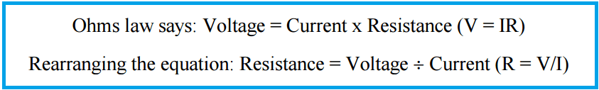
The true 4-wire measurement uses the current-potential method. A current of known value (I+) is passed through the sensor along the “current” lead wires. The voltage generated across the sensor is measured using the “potential” lead wires (Vsensor) and the sensor’s resistance is calculated by dividing the measured voltage by the Known current.

Four Wire RTD Principle

4 Wire RTD Formula

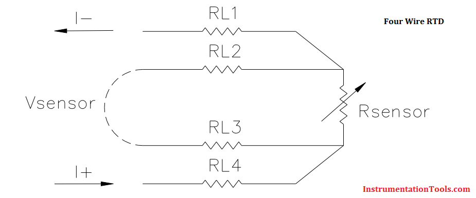
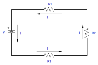
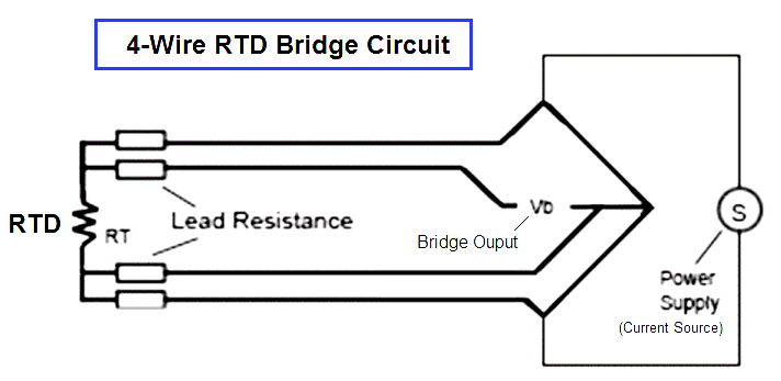
The 4-wire circuit is a true 4-wire bridge, which works by using wires 1 & 4 to power the circuit and wires 2 & 3 to read. This true bridge method will compensate for any differences in lead wire resistances.

The resistance of the lead wires is not a factor because:

  • The value of the current is equal at any point in the circuit. It is independent of the resistance of the lead wire.
  • The input impedance of the voltage measurement circuitry is high enough to prevent any significant current flow in the voltage leads. Since no current is flowing, the voltage along the potential leads does not change along their length.

4-wire RTD Bridge Circuit

4-wire RTD Bridge Circuit

Also Read: 2 Wire Vs 3 Wire Vs 4 Wire RTD’s

Don't Miss Our Updates
Be the first to get exclusive content straight to your email.
We promise not to spam you. You can unsubscribe at any time.
Invalid email address
You've successfully subscribed !
Thermocouple Software compensation
Thermocouple Calibration
How 3 Wire RTD Lead Wire Resistance Eliminated?
RTD Sensor Connections
Resistance Temperature Detectors Troubleshooting Tips
Share This Article
Facebook Whatsapp Whatsapp LinkedIn Copy Link
Share
Leave a Comment

Leave a Reply Cancel reply

Your email address will not be published. Required fields are marked *

Stay Connected

128.3kFollowersLike
69.1kFollowersFollow
208kSubscribersSubscribe
38kFollowersFollow

Categories

Recent Comments

  • Kamli on Top Free PLC Software
  • Guifty Shimica on Top Non-PLC Certification Courses for Automation Professionals
  • Guifty Shimica on Top Non-PLC Certification Courses for Automation Professionals
  • MIHARITSOA Aina Sitraka on Top Non-PLC Certification Courses for Automation Professionals

Related Articles

non-contact pyrometer principle

Non-contact Temperature Sensors

thermocouple voltages

Manually Interpreting Thermocouple Voltages

Temperature Sensors Fault

18 Temperature Sensors Fault Leads to Plant Shutdown

Thermocouples Green Rot Effect

Thermocouples Green Rot Effect

Pressure and Temperature Gauges

Pressure and Temperature Gauges

PTC NTC Thermistors Comparation

Thermistor Working Principle

Thermocouple Types

Types of Thermocouples

Measuring temperature with RTD

How RTD Measuring the Temperature

More Articles

Why Three-phase Voltage is 440 Volts

Why Three-phase Voltage is 440 Volts?

300 Power Electronics Projects - Top Electrical Major Project Titles

300 Power Electronics Projects – Top Electrical Major Project Titles

Electrical Machines Questions and Answers

DC Machines Efficiency and Testing Quiz

IEC 60909 and IEC 61363 for Short Circuit

Difference Between IEC 60909 and IEC 61363 for Short Circuit

Routine Tests of Transformers

Transformer Testing – Routine Tests of Transformers

Solve Pressure Control System Problems

Pressure Control System Problems

Calibrating Transmitter System One Seal with suppressed Zero

Calibrating Level Transmitter with Remote Seals

What is a cable gland?

How Many Types of Cable Glands Are There?

Follow US
All rights reserved. Reproduction in whole or in part without written permission is prohibited.
Welcome Back!

Sign in to your account

Username or Email Address
Password

Lost your password?