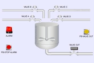
This fluid diagram shows the components and connections of a Bettis self-contained hydraulic module used to automatically shut off a “line valve” on a natural gas pipeline in the event of the pipeline pressure going outside of its limits (either falling below the low-pressure limit or rising above the high-pressure limit):
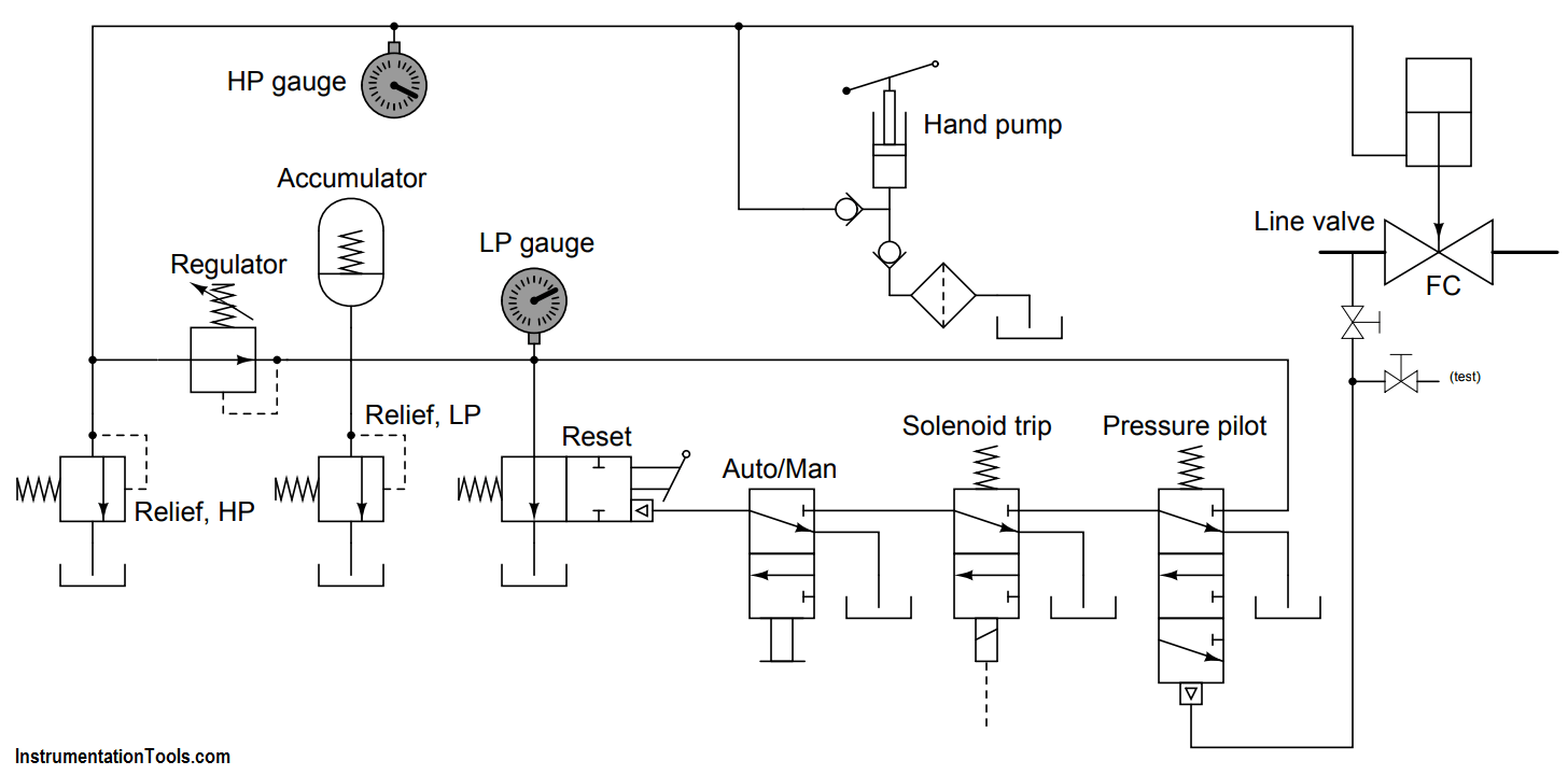
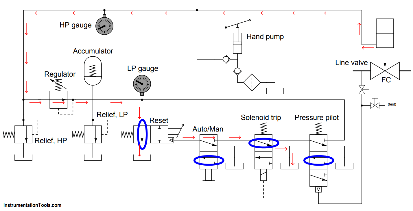
Identify all spool valve positions, and also trace the direction of oil flow, following a solenoid “trip” event.
Answer :
Read All SOV Questions & Answers