Inst ToolsInst ToolsInst Tools
  • Ask
  • Courses
  • Videos
  • Q & A
    • Interview
      • Instrumentation
      • Electronics
      • Electrical
      • Practical Questions
    • MCQ
      • Instrumentation MCQ
      • Electrical MCQ
      • Electronics MCQ
      • Control Systems MCQ
      • Analog Electronics MCQ
      • Digital Electronics MCQ
      • Power Electronics MCQ
      • Microprocessor MCQ
      • Multiple Choice Questions
  • EE
    • Electronics
      • Electronics Q & A
      • Electronic Basics
      • Electronic Devices & Circuits
      • Electronics Animation
      • Digital Electronics
    • Electrical
      • Electrical Basics
      • Electrical Q & A
      • Power Electronics
      • Electrical Machines
      • Electrical Animation
      • Power Systems
      • Switchgear & Protection
      • Transmission & Distribution
  • Measure
    • Control Valves
    • Calibration
    • Temperature
    • Pressure
    • Flow
    • Level
    • Analyzers
    • Switches
    • Vibration
    • Solenoid Valve
  • Control
    • PLC Tutorials
    • Control Systems
    • Safety Instrumented System (SIS)
    • Communication
    • Fire & Gas System
  • More
    • Design
    • Tools
    • Animation
    • Basics
    • Formulas
    • Standards
    • TextBooks
    • Common
    • Software
    • Excel Tools
    • Erection & Commissioning
    • Process Fundamentals
    • Videos
    • Books
Search
All rights reserved. Reproduction in whole or in part without written permission is prohibited.
Reading: Lower Explosive Limit (LEL)
Share
Notification Show More
Font ResizerAa
Inst ToolsInst Tools
Font ResizerAa
  • Courses
  • PLC Tutorials
  • Control Systems
Search
  • Ask
  • Courses
  • Videos
  • Q & A
    • Interview
    • MCQ
  • EE
    • Electronics
    • Electrical
  • Measure
    • Control Valves
    • Calibration
    • Temperature
    • Pressure
    • Flow
    • Level
    • Analyzers
    • Switches
    • Vibration
    • Solenoid Valve
  • Control
    • PLC Tutorials
    • Control Systems
    • Safety Instrumented System (SIS)
    • Communication
    • Fire & Gas System
  • More
    • Design
    • Tools
    • Animation
    • Basics
    • Formulas
    • Standards
    • TextBooks
    • Common
    • Software
    • Excel Tools
    • Erection & Commissioning
    • Process Fundamentals
    • Videos
    • Books
Follow US
All rights reserved. Reproduction in whole or in part without written permission is prohibited.
Inst Tools > Blog > Fire & Gas System > Lower Explosive Limit (LEL)

Lower Explosive Limit (LEL)

Last updated: May 31, 2019 5:20 pm
Editorial Staff
Fire & Gas System
No Comments
Share
4 Min Read
SHARE

The minimum concentration of a flammable gas in air capable of igniting is called the Lower Explosive Limit, or LEL.

This limit varies with the type of gas and with the oxygen concentration of the air in which the flammable gas is mixed.

Sensors designed to detect the dangerous presence of combustible gases are therefore called “LEL sensors.”

LEL monitors are used whenever there is a high probability of explosive gases present in the air.

These areas are referred to as classified areas in industry, and are precisely defined for safety engineering purposes.

Classified areas harboring explosive gases or vapors are deemed Class I areas, with different “Group” categories delineating the specific gas or vapor types involved.

Gases and vapors are not the only substances with the potential to explode in sufficient concentration.

Certain dusts (such as grain) and fibers (such as cotton) may also present explosion hazards if present in sufficient quantity.

Unfortunately, the majority of analytical technologies used to monitor lower explosive limits for safety purposes only function with gases and vapors (Class I), not dusts or fibers (Class II and Class III, respectively).

Popular sensor technologies used to detect the presence of combustibles in air include the following:

  • Catalytic bead
  • Infrared
  • Flame ionization
  • Thermocouple

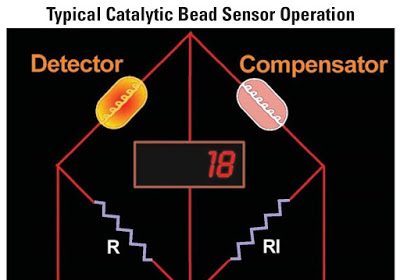
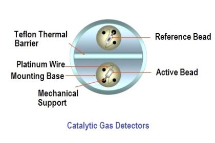
Catalytic bead and thermocouple sensors both function on the principle of heat generated during combustion.

Air potentially containing a concentration of flammable gases or vapors passes near a heated element, and any combustion occurring at that point will cause the local temperature to immediately rise.

These sensors must be designed in such a way they will not initiate an explosion, but merely combust the sample in a safe and measurable manner.

Like micro fuel cell oxygen sensors, these sensors may be manufactured in sufficiently small and rugged packages to enable their use as portable LEL sensors.

Infrared analyzers exploit the phenomenon of infrared (IR) light absorption by certain types of flammable gases and vapors.

A beam of infrared light passed across a sample of air will diminish in intensity if significant concentrations of the combustible substance exist in that sample.

Measuring this attenuation provides an indirect measurement of explosive potential.

A major disadvantage of this technique is that many non-flammable gases and vapors also absorb IR light, including carbon dioxide and water vapor.

In order to successfully reject these non-flammable substances, the analyzer must use very specific wavelengths of IR light, tuned to the specific substances of interest (and/or wavelengths tuned specifically to the substances of non-interest, as a compensating reference signal for the wavelengths captured by both the substances of interest and the substances of non-interest).

Flame ionization sensors work on the same principle as FIDs for chromatographs: a non-ionizing flame (usually fueled by hydrogen gas) will generate detectable ions only in the presence of air samples containing an ionizing fuel (such as a hydrocarbon gas). Of course, this form of LEL sensor is useless to detect hydrogen gas.

Also Read : Importance of LEL in F&G

Don't Miss Our Updates
Be the first to get exclusive content straight to your email.
We promise not to spam you. You can unsubscribe at any time.
Invalid email address
You've successfully subscribed !
How to identify location of Fire Detectors
Carbon Monoxide Gas Sensor Principle
Argonite Fire Suppression System Working Principle
Types of Fire Detectors
Fire and Gas system Audible and Visual Alarms
Share This Article
Facebook Whatsapp Whatsapp LinkedIn Copy Link
Share
Leave a Comment

Leave a Reply Cancel reply

Your email address will not be published. Required fields are marked *

Stay Connected

128.3kFollowersLike
69.1kFollowersFollow
208kSubscribersSubscribe
38kFollowersFollow

Categories

Recent Comments

  • Kamli on Top Free PLC Software
  • Guifty Shimica on Top Non-PLC Certification Courses for Automation Professionals
  • Guifty Shimica on Top Non-PLC Certification Courses for Automation Professionals
  • MIHARITSOA Aina Sitraka on Top Non-PLC Certification Courses for Automation Professionals

Related Articles

Smoke Detector Testing Procedure

Smoke Detector Testing Procedure

Infrared Hydrocarbon Gas Detector Calibration Procedure

Infrared Hydrocarbon Gas Detector Calibration Procedure

Fire Alarm System Commissioning Procedure

Fire Alarm System Commissioning Procedure

Selection of Fire and Gas Detectors

Basic Guidelines for Selection of Fire and Gas Detectors

Linear Heat Detector Working Principle

What are Linear Heat Detectors?

Design Basis for Fire Detection and Alarm System

Design Basis for Fire Detection and Alarm System

Flame Detectors Working Principle

Flame Detectors Working Principle

Difference Between Passive and Active Fire Protection

Active and Passive Fire Protection

More Articles

Alarm Management System

What is Alarm Management System ?

Metric Prefixes and Unit Conversions

Metric Prefixes and Unit Conversions

Redundant Power Supply WITH Diode Unit

Redundant Power Supply for Critical Field Panels

Instruments Troubleshooting - Problems, Causes, Corrective Actions

Instruments Troubleshooting – Problems, Causes, Corrective Actions

pH Analyzers Questions and Answers

Combination Electrode Questions & Answers

DP Transmitter Wet Leg Compensating Impulse Line

Questions on DP Transmitter Wet Leg Compensating Impulse Line

Calculate the 0%, 50%, and 100% Calibration Points

Calculate the 0%, 50%, and 100% Calibration Points

Field Instrument package

Package System Architecture – Control & Instrumentation

Follow US
All rights reserved. Reproduction in whole or in part without written permission is prohibited.
Welcome Back!

Sign in to your account

Username or Email Address
Password

Lost your password?