As the old saying goes, “If you have enough time to do something over again, you had enough time to do it right the first time.”
Today business moves at a highly accelerated rate, particularly in the process industries, compared to even just a decade ago. Companies often demand that product be shipped overnight, spending exorbitant amounts of money on priority freight. In an effort to accommodate the customer, most salespeople do not question the application for which the component(s) will be used. If pipe or fittings are being ordered, this does not usually create a problem. But when valves are concerned, this lack of scrutiny can result in problems of nightmarish proportions.

It behooves all parties involved to ask a few simple questions, and prevent the mistakes that can lead to disaster in a flow control system.
The Top Five Mistakes
1. The Name Game: Too many synonyms!
This is a case of “You say ‘po-tay-to’ I say ‘po-tah-to’.” Take pressure regulators, for example. Somebody might call it a “pressure sustaining valve,” still another might know it as a “pressure reducer valve.”
To muddy the waters even further, backpressure regulators are commonly mistaken for pressure regulators. The backpressure regulator is a normally closed valve installed at the END of a piping system to provide an obstruction to flow, and thereby regulate upstream (back) pressure. This valve is called upon to provide pressure in order to draw fluid off the system. The pressure regulator is a normally open valve and is installed at the START of a system or before pressure sensitive equipment to regulate or reduce undesirable higher upstream pressure.
Because of this “name game,” a normally open pressure regulator is sometimes installed to perform as a backpressure regulator, where it simply passes the fluid to the return tank and therefore does not maintain any pressure upstream.
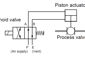
Solenoid valves are often misapplied as well. Generally, a solenoid valve is required to default to a desired position, referred to as fail-safe, upon loss of power. In the case of a two-way valve, either closed or open, or a three-way valve, either left port or right port. Even the relatively universal “energize to open” is ocassionally incorrectly ordered as “normally open.” In some of these cases, the process control system will compensate for the one valve operating improperly, but in the event of a power loss the results might be disastrous.
The question to ask: What is the valve to accomplish? In the case of a pressure regulator, will it be used to control pressure downstream or upstream? Does that actuated valve need to shut off or divert flow? Understand and write out precisely what function the valve is to perform.
2. Irreconcilable Differences: Media and Material
“If PVC works so well with water, why is my system is falling apart?!” So we ask: “Are there any impurities in your water?” The reply: “Of course not…and we keep it right at the boiling point!”
Even though this example sounds too absurd to be true, less obvious but equally ludicrous “time bombs” are installed around the world with alarming regularity.
Material compatibility is critical to the safe operation of a system and personnel safety. The result of a material misapplication can be catastrophic. Corroding pipe and valves can cause chemical leaks, which may injure workers, cause productivity losses and require reporting to OSHA and the EPA. Additional expenses for clean up of the chemical spills and fines may also be expected.
Proper material compatibility analysis requires knowledge of the type, concentration and temperature of fluid(s) being handled and the valve body and seal material. Every materials manufacturer publishes an easy to use chemical compatibility chart, which takes the guesswork out of specifying compatible materials. Unfortunately, anxious designers are notorious for ignoring the published temperature ratings of valve and seal materials, assuming that they all have a built in safety factor.
3. Size Matters…But Sometimes Pressure Matters More
If the pipe diameter is 2″, most people assume that a 2″ valve will do the job. In a few cases, that’s true. But in general, pressure considerations are of utmost importance in a piping system, and therefore critical when specifying a valve. Unfortunately, there are no industry-wide standard pressures for valve sizes; no two manufacturers design a 2″ valve the same way, and different designs have different pressure considerations.
Outlet pressure, for example, is critical to solenoid valves but frequently overlooked. If downstream pressure sufficiently exceeds the valve’s outlet pressure rating, the core spring may not be powerful enough to close the valve. In the case of a pilot-operated solenoid valve, however, an unusually low inlet pressure can be just as problematic. If the pilot valve requires 5 PSI pressure drop (delta P) to operate the main orifice, and the system has only 3 PSI, the valve may not open.
The factors to consider before specifying a valve are minimum and maximum inlet pressures, minimum and maximum differential pressure, outlet or backpressures and set pressure.
4. The Autobahn in Disguise
Velocity is very often overlooked when specifying a valve. Unlike that famous European roadway, a piping system does have a “speed limit.” The generally accepted safe velocity for a thermoplastic piping system is 5 feet per second. But like the pace of today’s business environment, a “slow” 5 ft/second process system just isn’t productive enough! Unfortunately, it is becoming the rare exception to the rule.
At higher velocities, such as an ultra-pure water system in a semiconductor fab facility, an improperly selected valve can easily create a water hammer situation if it closes too quickly. This dangerous energy surge travels at the speed of sound and frequently causes damage to pipe, fittings, valves, and instrumentation.
A classic example of this happened in a reverse osmosis water system at a major New York City hospital. Water was piped down to a sub-basement from storage tanks on the 16th floor. As the RO water was needed, a ball valve was opened, which ultimately fed a tiny gooseneck faucet. Unfortunately, the system designer didn’t take the 16 floors of head into consideration. Every time the ball valve was opened, water slammed into the constriction caused by the gooseneck faucet, which resulted in a dangerous water hammer back through the system.
The problem could have been prevented with a little planning. Always consider liquid velocity, and valve closing time.
5. Letting the Electric Slide
Neglect of actuator voltages and electrical enclosure types is not quite as common as the mistakes above, but often creates the most headaches and is potentially the most dangerous.
If an incorrect voltage is specified on a solenoid valve or a valve actuated by an electric motor, it will not operate properly. Often the actuator or coil will overheat, and may cause a fire.
NEMA ratings on electrically actuated valves are designed to provide for safety. NEMA has ratings for many types of electrical enclosures for a variety of environments. Most common are general purpose, watertight, corrosion resistant, and explosion proof. Specifying the wrong enclosure type may endanger personnel and property.
In Review…
Too often, valves are purchased by pipe size and without enough consideration for pressure, flow, chemical compatibility, performance, or safety factors. The mistakes listed above are just the most common—and most obvious. To properly specify a valve, all components and aspects of the system should be taken into consideration.
Also Read: Why Valve Type Matters ?


and voltage of solnoid maybe