Inst ToolsInst ToolsInst Tools
  • Courses
  • Automation
    • PLC
    • Control System
    • Safety System
    • Communication
    • Fire & Gas System
  • Instrumentation
    • Design
    • Pressure
    • Temperature
    • Flow
    • Level
    • Vibration
    • Analyzer
    • Control Valve
    • Switch
    • Calibration
    • Erection & Commissioning
  • Interview
    • Instrumentation
    • Electrical
    • Electronics
    • Practical
  • Q&A
    • Instrumentation
    • Control System
    • Electrical
    • Electronics
    • Analog Electronics
    • Digital Electronics
    • Power Electronics
    • Microprocessor
Search
  • Books
  • Software
  • Projects
  • Process
  • Tools
  • Basics
  • Formula
  • Power Plant
  • Root Cause Analysis
  • Electrical Basics
  • Animation
  • Standards
  • 4-20 mA Course
  • Siemens PLC Course
Reading: The inverse z-transform & Response of Linear Discrete Systems
Share
Notification Show More
Font ResizerAa
Inst ToolsInst Tools
Font ResizerAa
  • Courses
  • Design
  • PLC
  • Interview
  • Control System
Search
  • Courses
  • Automation
    • PLC
    • Control System
    • Safety System
    • Communication
    • Fire & Gas System
  • Instrumentation
    • Design
    • Pressure
    • Temperature
    • Flow
    • Level
    • Vibration
    • Analyzer
    • Control Valve
    • Switch
    • Calibration
    • Erection & Commissioning
  • Interview
    • Instrumentation
    • Electrical
    • Electronics
    • Practical
  • Q&A
    • Instrumentation
    • Control System
    • Electrical
    • Electronics
    • Analog Electronics
    • Digital Electronics
    • Power Electronics
    • Microprocessor
Follow US
All rights reserved. Reproduction in whole or in part without written permission is prohibited.
Inst Tools > Blog > Multiple Choice Questions > The inverse z-transform & Response of Linear Discrete Systems

The inverse z-transform & Response of Linear Discrete Systems

Last updated: November 27, 2021 5:40 pm
Editorial Staff
Multiple Choice Questions
No Comments
Share
5 Min Read
SHARE

The inverse z-transform & Response of Linear Discrete Systems

1. Unit step response of the system described by the equation y(n) +y(n-1) =x(n) is:

a) z2/(z+1)(z-1)
b) z/(z+1)(z-1)
c) z+1/z-1
d) z(z-1)/z+1

Answer: a

Explanation: Response of the system is calculated by taking the z-transform of the equation and input to the transfer function in the step input.

2. Inverse z-transform of the system can be calculated using:

a) Partial fraction method
b) Long division method
c) Basic formula of the z-transform
d) All of the mentioned

Answer: d

Explanation: Inverse z-transform is the opposite method of converting the transfer function in Z domain to the discrete time domain and this can be calculated using all the above formulas.

3. Assertion (A): The system function
H(z) = z3-2z2+z/z2+1/4z+1/s is not causal
Reason (R): If the numerator of H (z) is of lower order than the denominator, the system may be causal.

a) Both A and R are true and R is correct explanation of A
b) Both A and R are true and R is not correct Explanation of A
c) A is True and R is false
d) A is False and R is true

Answer: a

Explanation: The transfer function is not causal as for causality the numerator of H (z) is of lower order than the denominator, the system may be causal.

4. Assertion (A): Z-transform is used to analyze discrete time systems and it is also called pulsed transfer function approach.
Reason(R): The sampled signal is assumed to be a train of impulses whose strengths, or areas, are equal to the continuous time signal at the sampling instants.

a) Both A and R are true and R is correct explanation of A
b) Both A and R are true and R is not correct Explanation of A
c) A is True and R is false
d) A is False and R is true

Answer: a

Explanation: Z-transform is used to convert the discrete time systems into the z domain and it is also called pulsed transfer function approach that is justified only at the sampling instants.

5. The z-transform corresponding to the Laplace transform G(s) =10/s(s+5) is
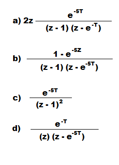
Answer: b

Explanation: Laplace transform is the technique of relating continuous time to the frequency domain while the z transform is relating discrete time hence Laplace transform is first converted into time domain and then the z transform is calculated.

6. Homogeneous solution of: y(n) -9/16y(n-2) = x(n-1)

a) C1(3/4)n+C2(3/4)-n
b) C1-(3/4)n-1+C2(3/4)n-1
c) C1(3/4)n
d) C1-(3/4)n

Answer: a

Explanation: Taking the z-transform of the given difference equation and solving the homogeneous equation and finding the solution using complimentary function.

7. If the z transform of x(n) is X(z) =z(8z-7)/4z2-7z+3, then the final value theorem is :

a) 1
b) 2
c) ∞
d) 0

Answer: a

Explanation: Final value theorem is calculated for the transfer function by equating the value of z as 1 and this can be calculated only for stable systems.

8. Final value theorem is used for:

a) All type of systems
b) Stable systems
c) Unstable systems
d) Marginally stable systems

Answer: b

Explanation: Final value theorem is used to calculate the final value as for time infinite and for z = 1 the final value theorem can be calculated and final value theorem is for for stable systems.

9. If the z-transform of the system is given by H (z) = a+z-1/1+az-1 . Where a is real valued:

a) A low pass filter
b) A high pass filter
c) An all pass filter
d) A bandpass filter

Answer: c

Explanation: The discrete time frequency response will be aperiodic and does not depend on the frequency and the transfer function will be representing the all pass filter.

10. The system is stable if the pole of the z-transform lies inside the unit circle

a) True
b) False

Answer: a

Explanation: For the system to be stable in Z domain the pole in the this domain must lie inside the unit circle and for the causal stable region must be outside the circle and hence the locus will be a ring.

Don't Miss Our Updates
Be the first to get exclusive content straight to your email.
We promise not to spam you. You can unsubscribe at any time.
Invalid email address
You've successfully subscribed !

Continue Reading

Magnetic Wind Instruments Questions & Answers
Root Locus in Control Systems
Gas Chromatography Questions & Answers
X-Ray Diffractometers Questions & Answers
Experimentation of Transfer Function
Electron Spectroscopy for Chemical Analysis
Share This Article
Facebook Whatsapp Whatsapp LinkedIn Copy Link
Share
Leave a Comment

Leave a Reply Cancel reply

Your email address will not be published. Required fields are marked *

Stay Connected

128.3kFollowersLike
69.1kFollowersFollow
208kSubscribersSubscribe
38kFollowersFollow

Categories

Explore More

Total Reflection Spectrometer Questions & Answers
Stability of Nonlinear System – II
Optimal Control Problems – Part 1
Gamma Camera Questions & Answers
Controller Components – Part 1 Objective Questions
Flow Measurement Multiple Choice Questions
Auger Electron Spectroscopy
H2S Analyzers Questions & Answers

Keep Learning

Mass Spectrometer Questions and Answers

Gas Chromatograph- Mass Spectrometer

Stepper Motor Parts

Stepper Motor MCQ

Analyzers Questions and Answers

Pulse Height Analyzer Questions & Answers

Digital Control Systems

The Z-Transfer Function

Ion Spectrometers Questions & Answers

Instrumentation for Electron Spectroscopy

Feedback Characteristics of Control Systems

Linear Approximation of the Non-Linear System MCQ

Chromatography Questions & Answers

Gas Solid Chromatography Questions & Answers

Chromatography Questions & Answers

Operation of Chromatography Questions & Answers

Learn More

PLC SCADA Water Pump

PLC Program for Controlling a Water Pump with 3 Power Sources

De-energized Electrical Circuits

De-energized Electrical Circuits, Networks, and Equipment

Three Phase AC Generators

Three Phase AC Generators

How a Diode Works Animation

How a Gate Works ?

overview-of-communication-protocols

Industrial Automation Communication Protocols

PLC Ladder Logic Simulator Mobile Apps For Android

PLC Ladder Logic Simulator Mobile Apps For Android

Filtering and Dynamic Compensation Objective Questions

Filtering and Dynamic Compensation Objective Questions

Crowbar fault protection circuit

Crowbar fault protection circuit

Follow US
All rights reserved. Reproduction in whole or in part without written permission is prohibited.
Welcome Back!

Sign in to your account

Username or Email Address
Password

Lost your password?