Inst ToolsInst ToolsInst Tools
  • Ask
  • Courses
  • Videos
  • Q & A
    • Interview
      • Instrumentation
      • Electronics
      • Electrical
      • Practical Questions
    • MCQ
      • Instrumentation MCQ
      • Electrical MCQ
      • Electronics MCQ
      • Control Systems MCQ
      • Analog Electronics MCQ
      • Digital Electronics MCQ
      • Power Electronics MCQ
      • Microprocessor MCQ
      • Multiple Choice Questions
  • EE
    • Electronics
      • Electronics Q & A
      • Electronic Basics
      • Electronic Devices & Circuits
      • Electronics Animation
      • Digital Electronics
    • Electrical
      • Electrical Basics
      • Electrical Q & A
      • Power Electronics
      • Electrical Machines
      • Electrical Animation
      • Power Systems
      • Switchgear & Protection
      • Transmission & Distribution
  • Measure
    • Control Valves
    • Calibration
    • Temperature
    • Pressure
    • Flow
    • Level
    • Analyzers
    • Switches
    • Vibration
    • Solenoid Valve
  • Control
    • PLC Tutorials
    • Control Systems
    • Safety Instrumented System (SIS)
    • Communication
    • Fire & Gas System
  • More
    • Design
    • Tools
    • Animation
    • Basics
    • Formulas
    • Standards
    • TextBooks
    • Common
    • Software
    • Excel Tools
    • Erection & Commissioning
    • Process Fundamentals
    • Videos
    • Books
Search
All rights reserved. Reproduction in whole or in part without written permission is prohibited.
Reading: Pressure Transmitters Filled impulse lines
Share
Notification Show More
Font ResizerAa
Inst ToolsInst Tools
Font ResizerAa
  • Courses
  • PLC Tutorials
  • Control Systems
Search
  • Ask
  • Courses
  • Videos
  • Q & A
    • Interview
    • MCQ
  • EE
    • Electronics
    • Electrical
  • Measure
    • Control Valves
    • Calibration
    • Temperature
    • Pressure
    • Flow
    • Level
    • Analyzers
    • Switches
    • Vibration
    • Solenoid Valve
  • Control
    • PLC Tutorials
    • Control Systems
    • Safety Instrumented System (SIS)
    • Communication
    • Fire & Gas System
  • More
    • Design
    • Tools
    • Animation
    • Basics
    • Formulas
    • Standards
    • TextBooks
    • Common
    • Software
    • Excel Tools
    • Erection & Commissioning
    • Process Fundamentals
    • Videos
    • Books
Follow US
All rights reserved. Reproduction in whole or in part without written permission is prohibited.
Inst Tools > Blog > Pressure Measurement > Pressure Transmitters Filled impulse lines

Pressure Transmitters Filled impulse lines

Last updated: June 26, 2018 2:27 pm
Editorial Staff
Pressure Measurement
1 Comment
Share
4 Min Read
SHARE

An alternate method for isolating a pressure-sensing instrument from direct contact with process fluid is to fill the impulse lines with a harmless fluid, which in turn directly contacts the process fluid. Filling impulse tubes with a static fluid works when gravity is able to keep the fill fluid in place, such as in this example of a pressure transmitter connected to a water pipe by a glycerin-filled impulse line:

Pressure Transmitters Filled impulse lines

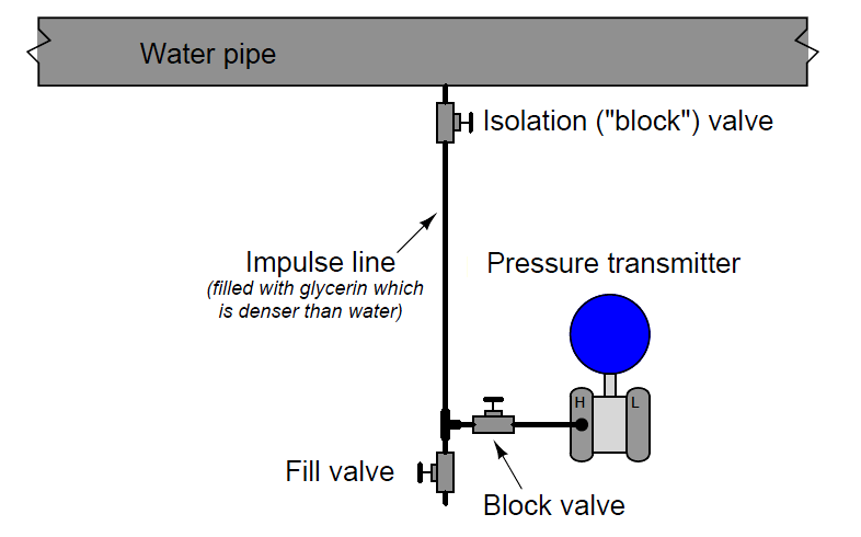
A reason someone might do this is for freeze protection, since glycerin freezes at a lower temperature than water. If the impulse line were filled with process water, it might freeze solid in cold weather conditions (the water in the pipe cannot freeze so long as it is forced to flow). The greater density of glycerin keeps it placed in the impulse line, below the process water line. A fill valve is provided near the transmitter so a technician may re-fill the impulse line with glycerin (using a hand pump) if ever needed.

As with a remote diaphragm, a filled impulse line will generate its own pressure proportional to the height difference between the point of process connection and the pressure-sensing element. If the height difference is substantial, the pressure offset resulting from this difference in elevation will require compensation by means of an intentional “zero shift” of the pressure instrument when it is calibrated.

With no isolating diaphragm to separate process fluid from the fill fluid, it is critical that the fill fluid be compatible (Note )  with the process fluid. Not only does this imply a total lack of chemical reactivity between the two fluids, but it also means the two fluids should not be readily miscible (capable of mixing in any proportion).

Note : Truth be told, this is a requirement for all pressure transmitter fill fluids even when isolating diaphragms are in place to prevent mixing of process and fill fluids, because no diaphragm is 100% guaranteed to seal forever. This means every pressure transmitter must be chosen for the application in mind, since modern DP transmitters all use fill fluid in their internal sensors, whether or not the impulse lines are also filled with a non-reactive fluid.

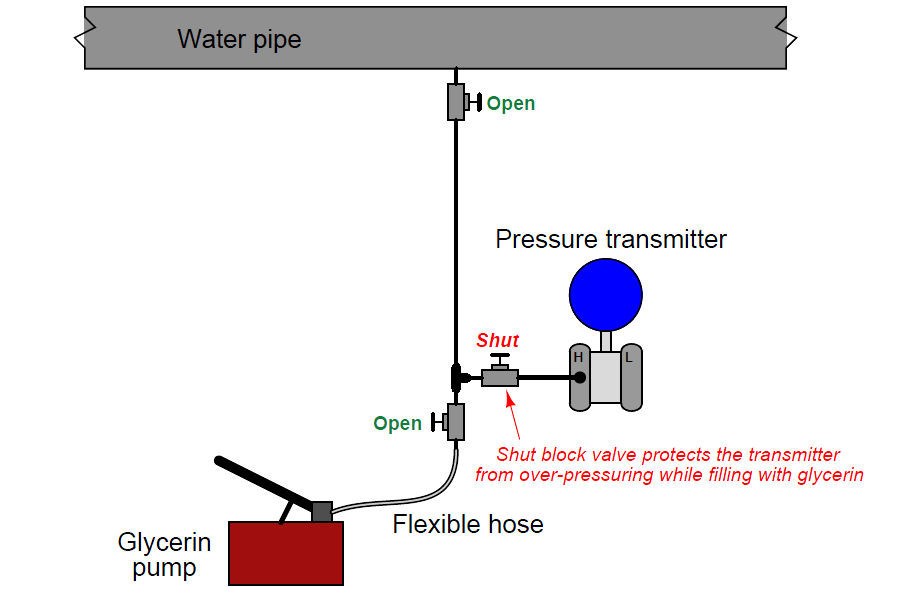
An important consideration in filled-line systems is how to refill the impulse line(s) without damaging the pressure instrument. Hand-operated pumps are commonly used to refill impulse lines, but such pumps are often capable of generating greater fluid pressures than the instrument can safely withstand. If we were to connect a glycerin pump to the filled system pictured previously, it would be advisable to shut the transmitter’s block valve to ensure we did not accidently over-pressure the transmitter. This is especially true if the impulse line happens to become plugged with debris, and substantial glycerin pressure from the hand pump is required to dislodge the blockage:

Pressure Transmitters Hand-operated pumps

In fact, the issue of impulse tube plugging is another reason to consider filled-line connections between pressure instruments and process lines or vessels. If ever a plug develops in the line, repumping the lines with fresh fill fluid is a practical way to clear the plug without disassembling any part of the system. For processes where impulse line plugging is a chronic problem, another solution exists called purging impulse lines.

 Credits : Tony R. Kuphaldt – Creative Commons Attribution 4.0 License

Don't Miss Our Updates
Be the first to get exclusive content straight to your email.
We promise not to spam you. You can unsubscribe at any time.
Invalid email address
You've successfully subscribed !
Types of Bourdon Tube
Purpose of Stop in a Pressure Measuring Instrument
How to Read Gauge Analog Scales
Diaphragm Pressure Sensors
Pressure Transmitters Heat-traced impulse lines
Share This Article
Facebook Whatsapp Whatsapp LinkedIn Copy Link
Share
1 Comment
  • M.Salauddin says:
    November 22, 2017 at 12:28 pm

    Also please specify about Hot climate variation in impulse line where temperature here reaches more than 50 deg c.

    Reply

Leave a Reply Cancel reply

Your email address will not be published. Required fields are marked *

Stay Connected

128.3kFollowersLike
69.1kFollowersFollow
208kSubscribersSubscribe
38kFollowersFollow

Categories

Recent Comments

  • Kamli on Top Free PLC Software
  • Guifty Shimica on Top Non-PLC Certification Courses for Automation Professionals
  • Guifty Shimica on Top Non-PLC Certification Courses for Automation Professionals
  • MIHARITSOA Aina Sitraka on Top Non-PLC Certification Courses for Automation Professionals

Related Articles

piping for a Different pressure flow transmitter

Impulse Piping standards for Field instruments

Pressure Measurement using Manometer

Pressure Measurement using Manometer

Pressure Gauge with Syphons

Pressure Gauge Syphons Principle

pressure gauge snubber

Pressure Gauge Snubbers

Pressure Gauge Maintenance and Troubleshooting

Pressure Gauge Maintenance and Troubleshooting

Pressure Detection Circuit

Pressure Detection Circuit

Pressure Sensor Temperature Effects

Temperature Compensation for Pressure Measurement

Pressure Gauge Calibration Procedure

More Articles

PLC Program for Positive edge pulse output for one scan cycle

PLC Program for Positive Edge Pulse Output for One Scan Cycle

Wrongly terminated Thermocouple (TC) wires

Too Low-Temperature Readings after a Failed Thermocouple Change

Calculate Temperature of RTD

Calculate Temperature of RTD

Calculate Power in Series RCL Circuit

Calculate Power in Series RCL Circuit

Pressure Reducing and Desuperheating Station (PRDS)

Pressure Reducing and DeSuperheating Station (PRDS)

Density Measurement using Remote Seal Transmitters

Remote Seal Differential Pressure Transmitters Principle

Instrumentation Engineering Materials Test

Instrumentation Engineering Materials Test

Power Electronics Objective Questions

Thyristor Firing Objective Questions

Follow US
All rights reserved. Reproduction in whole or in part without written permission is prohibited.
Welcome Back!

Sign in to your account

Username or Email Address
Password

Lost your password?