Inst ToolsInst ToolsInst Tools
  • Ask
  • Courses
  • Videos
  • Q & A
    • Interview
      • Instrumentation
      • Electronics
      • Electrical
      • Practical Questions
    • MCQ
      • Instrumentation MCQ
      • Electrical MCQ
      • Electronics MCQ
      • Control Systems MCQ
      • Analog Electronics MCQ
      • Digital Electronics MCQ
      • Power Electronics MCQ
      • Microprocessor MCQ
      • Multiple Choice Questions
  • EE
    • Electronics
      • Electronics Q & A
      • Electronic Basics
      • Electronic Devices & Circuits
      • Electronics Animation
      • Digital Electronics
    • Electrical
      • Electrical Basics
      • Electrical Q & A
      • Power Electronics
      • Electrical Machines
      • Electrical Animation
      • Power Systems
      • Switchgear & Protection
      • Transmission & Distribution
  • Measure
    • Control Valves
    • Calibration
    • Temperature
    • Pressure
    • Flow
    • Level
    • Analyzers
    • Switches
    • Vibration
    • Solenoid Valve
  • Control
    • PLC Tutorials
    • Control Systems
    • Safety Instrumented System (SIS)
    • Communication
    • Fire & Gas System
  • More
    • Design
    • Tools
    • Animation
    • Basics
    • Formulas
    • Standards
    • TextBooks
    • Common
    • Software
    • Excel Tools
    • Erection & Commissioning
    • Process Fundamentals
    • Videos
    • Books
Search
All rights reserved. Reproduction in whole or in part without written permission is prohibited.
Reading: Ripple Voltage in Rectifiers
Share
Notification Show More
Font ResizerAa
Inst ToolsInst Tools
Font ResizerAa
  • Courses
  • PLC Tutorials
  • Control Systems
Search
  • Ask
  • Courses
  • Videos
  • Q & A
    • Interview
    • MCQ
  • EE
    • Electronics
    • Electrical
  • Measure
    • Control Valves
    • Calibration
    • Temperature
    • Pressure
    • Flow
    • Level
    • Analyzers
    • Switches
    • Vibration
    • Solenoid Valve
  • Control
    • PLC Tutorials
    • Control Systems
    • Safety Instrumented System (SIS)
    • Communication
    • Fire & Gas System
  • More
    • Design
    • Tools
    • Animation
    • Basics
    • Formulas
    • Standards
    • TextBooks
    • Common
    • Software
    • Excel Tools
    • Erection & Commissioning
    • Process Fundamentals
    • Videos
    • Books
Follow US
All rights reserved. Reproduction in whole or in part without written permission is prohibited.
Inst Tools > Blog > Electronic Devices & Circuits > Ripple Voltage in Rectifiers

Ripple Voltage in Rectifiers

Last updated: October 4, 2016 1:33 pm
Editorial Staff
Electronic Devices & Circuits
No Comments
Share
2 Min Read
SHARE

Ripple Voltage As you have seen, the capacitor quickly charges at the beginning of a cycle and slowly discharges through RL after the positive peak of the input voltage (when the diode is reverse-biased). The variation in the capacitor voltage due to the charging and discharging is called the ripple voltage. Generally, ripple is undesirable; thus, the smaller the ripple, the better the filtering action, as illustrated in Below Figure.

rectifier-ripple-voltage

half-wave-rectifier-ripple-voltage

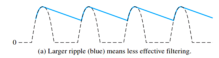
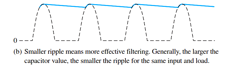
Fig : Half-wave ripple voltage (blue line).

For a given input frequency, the output frequency of a full-wave rectifier is twice that of a half-wave rectifier, as illustrated in Figure 1. This makes a full-wave rectifier easier to filter because of the shorter time between peaks. When filtered, the full-wave rectified voltage has a smaller ripple than does a half-wave voltage for the same load resistance and capacitor values. The capacitor discharges less during the shorter interval between full-wave pulses, as shown in Figure 2.

full-wave-rectifier-ripple-voltage

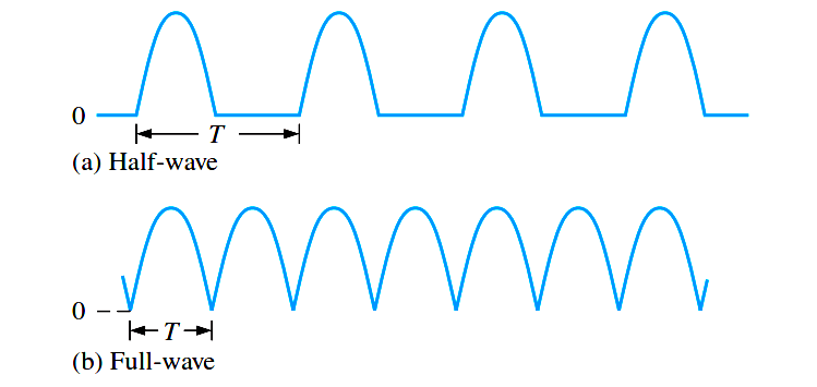
Fig 1 : The period of a full-wave rectified voltage is half that of a half-wave rectified voltage. The output frequency of a full-wave rectifier is twice that of a half-wave rectifier.

capacitor-filter-ripples

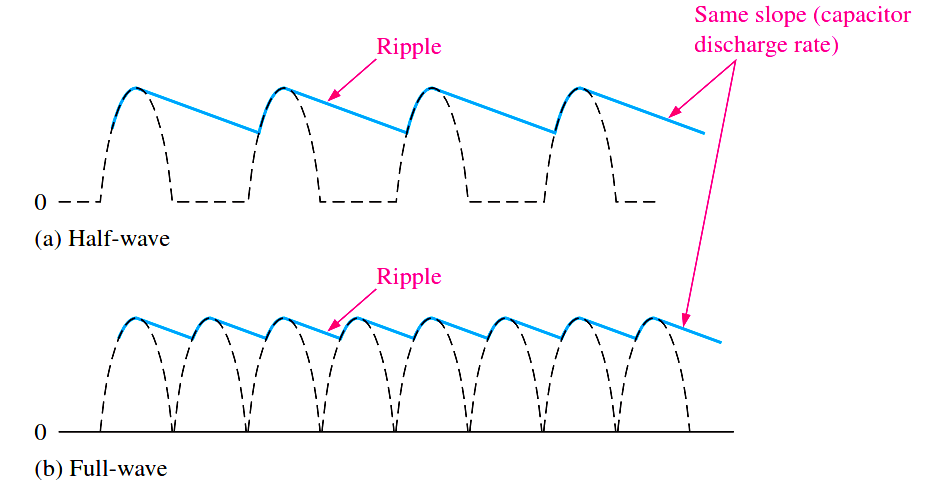
Fig 2 : Comparison of ripple voltages for half-wave and full-wave rectified voltages with the same filter capacitor and load and derived from the same sinusoidal input voltage.

Ripple Factor

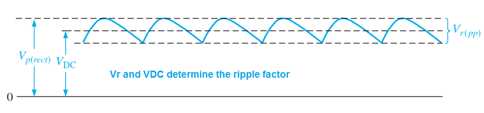
The ripple factor (r) is an indication of the effectiveness of the filter and is defined as

ripple-factor

where Vr(pp) is the peak-to-peak ripple voltage and VDC is the dc (average) value of the filter’s output voltage, as illustrated in Below Figure. The lower the ripple factor, the better the filter. The ripple factor can be lowered by increasing the value of the filter capacitor or increasing the load resistance.

ripple-factor-graph

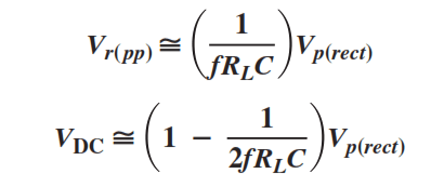
For a full-wave rectifier with a capacitor-input filter, approximations for the peak-to-peak ripple voltage, Vr(pp), and the dc value of the filter output voltage, VDC, are given in the following equations. The variable Vp(rect) is the unfiltered peak rectified voltage. Notice that if RL or C increases, the ripple voltage decreases and the dc voltage increases.

ripple-factors-equation

Don't Miss Our Updates
Be the first to get exclusive content straight to your email.
We promise not to spam you. You can unsubscribe at any time.
Invalid email address
You've successfully subscribed !
What is a Memristor? Principle, Advantages, Applications
Combining Independent Voltage Sources in Series
Transistor Voltage Divider Bias
Operation of Zener Diode Voltage Regulator
Transistor as Amplifier
Share This Article
Facebook Whatsapp Whatsapp LinkedIn Copy Link
Share
Leave a Comment

Leave a Reply Cancel reply

Your email address will not be published. Required fields are marked *

Stay Connected

128.3kFollowersLike
69.1kFollowersFollow
208kSubscribersSubscribe
38kFollowersFollow

Categories

Recent Comments

  • Guifty Shimica on Top Non-PLC Certification Courses for Automation Professionals
  • Guifty Shimica on Top Non-PLC Certification Courses for Automation Professionals
  • MIHARITSOA Aina Sitraka on Top Non-PLC Certification Courses for Automation Professionals
  • Vaishnavi on Free Instrumentation Course for Trainee Engineers

Related Articles

Full Wave Rectifier

Full Wave Rectifier

Photodiode as Variable Resistance Device

Photodiode as Variable Resistance Device

Transistor-cut-off-saturation-active-regions

Transistor Cut off, Saturation & Active Regions

Electron Gun of CRT

Electron Gun of Cathode Ray Tube

transistor-emitter-bias

Transistor Emitter Bias

photo-diode

Photodiode Working Principle

diode-clamper-circuit

Diode Clampers Principle

Fluorescent Screen of CRT

CRT Fluorescent Screen

More Articles

Water Treatment Plant SCADA

Typical HMI Screen Design for Water Treatment Plant

Electrical & Electronics Measurements Objective Questions

Electrical & Electronics Measurements Objective Questions – Set 6

PLC 1 Push Button to Turn ON or OFF 1 Output

PLC 1 Push Button to Turn ON or OFF 1 Output

Electrical Machines Questions and Answers

Hunting and Damper Windings Questions

Introduction to Schneider PLC

Different Types of Schneider PLC

Electric Motors Noises

Electric Motors Noises – Types, Possible Sources, Reasons

P&ID Guidelines for Pumps

P&ID Guidelines for Pumps

CNC Custom Machining

What is Custom Machining in CNC? Why Should You Choose It?

Follow US
All rights reserved. Reproduction in whole or in part without written permission is prohibited.
Welcome Back!

Sign in to your account

Username or Email Address
Password

Lost your password?