By using this site, you agree to the Privacy Policy and Terms of Use.
Accept
Inst ToolsInst ToolsInst Tools
  • Ask
  • Courses
  • Videos
  • Q & A
    • Interview
      • Instrumentation
      • Electronics
      • Electrical
      • Practical Questions
    • MCQ
      • Instrumentation MCQ
      • Electrical MCQ
      • Electronics MCQ
      • Control Systems MCQ
      • Analog Electronics MCQ
      • Digital Electronics MCQ
      • Power Electronics MCQ
      • Microprocessor MCQ
      • Multiple Choice Questions
  • EE
    • Electronics
      • Electronics Q & A
      • Electronic Basics
      • Electronic Devices & Circuits
      • Electronics Animation
      • Digital Electronics
    • Electrical
      • Electrical Basics
      • Electrical Q & A
      • Power Electronics
      • Electrical Machines
      • Electrical Animation
      • Power Systems
      • Switchgear & Protection
      • Transmission & Distribution
  • Measure
    • Control Valves
    • Calibration
    • Temperature
    • Pressure
    • Flow
    • Level
    • Analyzers
    • Switches
    • Vibration
    • Solenoid Valve
  • Control
    • PLC Tutorials
    • Control Systems
    • Safety Instrumented System (SIS)
    • Communication
    • Fire & Gas System
  • More
    • Design
    • Tools
    • Animation
    • Basics
    • Formulas
    • Standards
    • TextBooks
    • Common
    • Software
    • Excel Tools
    • Erection & Commissioning
    • Process Fundamentals
    • Videos
    • Books
Search
All rights reserved. Reproduction in whole or in part without written permission is prohibited.
Reading: 5 Valve Manifold Operation
Share
Notification Show More
Font ResizerAa
Inst ToolsInst Tools
Font ResizerAa
  • Ask
  • Courses
  • Videos
  • Q & A
  • EE
  • Measure
  • Control
  • More
Search
  • Ask
  • Courses
  • Videos
  • Q & A
    • Interview
    • MCQ
  • EE
    • Electronics
    • Electrical
  • Measure
    • Control Valves
    • Calibration
    • Temperature
    • Pressure
    • Flow
    • Level
    • Analyzers
    • Switches
    • Vibration
    • Solenoid Valve
  • Control
    • PLC Tutorials
    • Control Systems
    • Safety Instrumented System (SIS)
    • Communication
    • Fire & Gas System
  • More
    • Design
    • Tools
    • Animation
    • Basics
    • Formulas
    • Standards
    • TextBooks
    • Common
    • Software
    • Excel Tools
    • Erection & Commissioning
    • Process Fundamentals
    • Videos
    • Books
Follow US
All rights reserved. Reproduction in whole or in part without written permission is prohibited.
Inst Tools > Blog > Common > 5 Valve Manifold Operation
CommonPressure Measurement

5 Valve Manifold Operation

Last updated: March 27, 2019 3:08 pm
Editorial Staff
Share
2 Min Read
SHARE

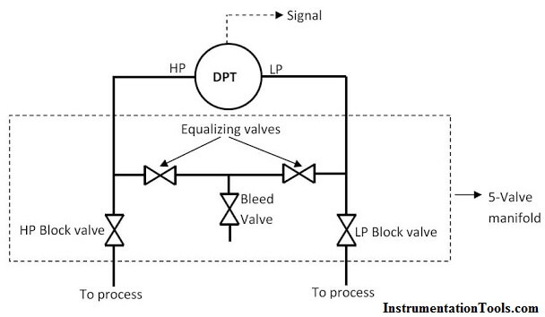
The 5-valve transmitter manifold is shown in the schematic below:

Contents
5 Valve ManifoldOperational Sequence for Valving DP Transmitter with a 5-Valve Manifold into Service:Removing the 5-Valve Manifold DP Transmitter from Service

5 Valve Manifold
5 Valve manifold

During normal operation, the HP and LP valves are open while the equalizing valves and the bleed valve are closed.

However, It is critically important that the equalizing valve(s) never be open while both block valves are open!

If the process fluid is dangerously hot or radioactive, a combination of open equalizing and block valves will let that dangerous fluid reach the transmitter and manifold, possibly causing damage or creating a personal hazard.

Operational Sequence for Valving DP Transmitter with a 5-Valve Manifold into Service:
  1. Check all valves HP,LP, the bleed valve and the equalizing valves are closed.
  2. Open the equalizing valves. This ensures that the same pressure will be applied to both sides of the transmitter, i.e. zero differential pressure.
  3. Open the High Pressure block valve slowly, check for leakage from both the high pressure and low-pressure side of the transmitter.
  4. Close the equalizing valves. This locks the pressure on both sides of the transmitter.
  5. Open the low-pressure block valve to apply process pressure to the low-pressure side of the transmitter and establish the working differential pressure.

The transmitter is now in service.

Removing the 5-Valve Manifold DP Transmitter from Service

The DP transmitter with a 5-Valve manifold can easily be removed from service using the steps outlined below:

  1. Close the HP and LP block valves.
  2. Open the equalizing valves.
  3. Open the bleed valve to vent process pressure to the atmosphere

The transmitter is now out of service. As is always the case, the transmitter capsule housing still contains process pressure; this will require bleeding.

Note that the 3-valve and 5-valve DP transmitter manifolds are usually manufactured as monolithic or single units. The schematics above are just for illustration and explanations.

 Also Read: 3 Valve Manifold Operation
Don't Miss Our Updates
Be the first to get exclusive content straight to your email.
We promise not to spam you. You can unsubscribe at any time.
Invalid email address
You've successfully subscribed !
Streams After Electrical Engineering Graduation
Vacuum Technology is Enabling New Era of Ultra-Powerful Computers: Quantum Computing
Closed Tank Remote Seal Capillary type DP Transmitter
Flange Types and Definitions
The Importance of Supply Chain Collaboration
Share This Article
Facebook Whatsapp Whatsapp LinkedIn Copy Link
Share
4 Comments
  • Thomas Culp says:
    October 24, 2016 at 7:46 pm

    The first paragraph is incorrect. If both the block and bleed ports are both open the process will bleed out possibly contacting the operator. Not the manifold and transmitter as stated.

    Reply
    • S Bharadwaj Reddy says:
      October 24, 2016 at 8:39 pm

      Hi Thomas, Yes, Thats why a Hazard is mentioned in end of the paragraph. Thanks

      Reply
  • Harshil Baxi says:
    June 16, 2018 at 7:33 am

    In 5 way manifold 1 st paragraph you have mentioned both block and equilization valve should not be opened at the same time but the reason is not proper.

    It should not because as If HP and LP are having differnet process fluid then they will mix together in system.

    Example
    Screw comressor PDI between Seal Oil and Reference Gas.In this case if we open equilization with block valve in opened condition then in compressor gas side Oil will carry forward.

    Reply
  • Isaac Donald says:
    November 22, 2018 at 6:48 pm

    Please I what to now, in a DPT transmitter the capsule side of HP and LP are they of the same tensile strain.

    Reply

Leave a Reply Cancel reply

Your email address will not be published. Required fields are marked *

Stay Connected

128.3kFollowersLike
69.1kFollowersFollow
206kSubscribersSubscribe
38kFollowersFollow

Latest

Top Non-PLC Certification Courses for Automation Professionals
Common
Things You Need to Know About DeviceNet
Communication
Why is IEC 60269 Important
Why is IEC 60269 Important? – Electrical Applications
Standards
NAMUR OPEN ARCHITECTURE
What is NAMUR OPEN ARCHITECTURE?
Control Systems

More Articles

Fieldbus and Profibus

Difference between Fieldbus and Profibus

Difference between LVDT and RVDT

Difference between LVDT and RVDT?

Time Response Analysis

Robotic Control System – Part I

Transformer Tap changer

Ferroresonance in Power Transformers

Effects of Capillary Tubing on Pressure Measurement

Capillary Tubing Pressure Sensor Temperature & Elevation Problems

Seven Segment Display Programming with Structured Text

Seven Segment Display Programming with Structured Text

Instrumentation loop Diagram

Instrumentation Loop Diagrams

Difference Between PLC and RTU

Difference Between PLC and RTU?

//

Inst Tools

Sign Up for Our Newsletter

Subscribe to our newsletter to get our newest articles instantly!

[mc4wp_form id=”847″]

Follow US
All rights reserved. Reproduction in whole or in part without written permission is prohibited.
Welcome Back!

Sign in to your account

Username or Email Address
Password

Lost your password?