Inst ToolsInst ToolsInst Tools
  • Courses
  • Automation
    • PLC
    • Control System
    • Safety System
    • Communication
    • Fire & Gas System
  • Instrumentation
    • Design
    • Pressure
    • Temperature
    • Flow
    • Level
    • Vibration
    • Analyzer
    • Control Valve
    • Switch
    • Calibration
    • Erection & Commissioning
  • Interview
    • Instrumentation
    • Electrical
    • Electronics
    • Practical
  • Q&A
    • Instrumentation
    • Control System
    • Electrical
    • Electronics
    • Analog Electronics
    • Digital Electronics
    • Power Electronics
    • Microprocessor
  • Request
Search
  • Books
  • Software
  • Projects
  • Process
  • Tools
  • Basics
  • Formula
  • Power Plant
  • Root Cause Analysis
  • Electrical Basics
  • Animation
  • Standards
  • 4-20 mA Course
  • Siemens PLC Course
Reading: What is a Fieldbus Terminator and How Does it Work?
Share
Font ResizerAa
Inst ToolsInst Tools
Font ResizerAa
  • Courses
  • Design
  • PLC
  • Interview
  • Control System
Search
  • Courses
  • Automation
    • PLC
    • Control System
    • Safety System
    • Communication
    • Fire & Gas System
  • Instrumentation
    • Design
    • Pressure
    • Temperature
    • Flow
    • Level
    • Vibration
    • Analyzer
    • Control Valve
    • Switch
    • Calibration
    • Erection & Commissioning
  • Interview
    • Instrumentation
    • Electrical
    • Electronics
    • Practical
  • Q&A
    • Instrumentation
    • Control System
    • Electrical
    • Electronics
    • Analog Electronics
    • Digital Electronics
    • Power Electronics
    • Microprocessor
  • Request
Follow US
All rights reserved. Reproduction in whole or in part without written permission is prohibited.
Inst Tools > Blog > Communication > What is a Fieldbus Terminator and How Does it Work?

What is a Fieldbus Terminator and How Does it Work?

Last updated: April 14, 2018 8:29 pm
Editorial Staff
Communication
1 Comment
Share
3 Min Read
SHARE

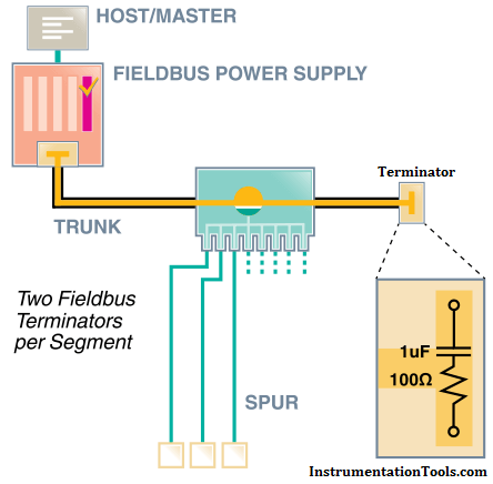
First let’s define exactly what a fieldbus terminator is. A fieldbus terminator is a component of a fieldbus system that is the equivalent of a 1 µF capacitor and a 100 Ω resistor in series with each other. The main functions of fieldbus terminators are to shunt the fieldbus current and to protect the fieldbus signal against electrical reflections.

Fieldbus Terminator

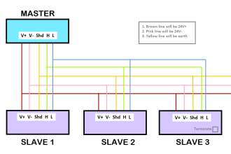
Each fieldbus segment needs exactly two terminators. These terminators are located at both the beginning of the segment and at the very end of the segment. Many times, the terminator located at the beginning of the segment is built into the fieldbus power supply modules, fieldbus power conditioners, or, in Pepperl+Fuchs’ case, it is built into the motherboard that houses the power supply modules and is activated by a simple switch. All of these methods for adding a terminator work well because they end up saving you from adding components to your overall system topology. The terminators located at the end of the segment are normally added as a standalone component or built into your distribution junction box.

The main purpose of fieldbus terminators is to act as a current shunt for the control network. Fieldbus devices communicate with other devices and the controller by changing their overall current draw. This modulating current passes across the terminators in the segment, resulting in the fieldbus signal voltage. Having too many (three or more) terminators results in a reduction in signal level. One extra terminator in the segment typically reduces the signal by about 30%. Failing to use terminators in your segment has the reverse effect and causes a large increase in signal level; approximately 70% for each missing terminator.

Fieldbus Terminator

Another function of the terminator is to reduce the impact of electrical reflections.Reflections on a control network are similar to waves in a pool. As a wave propagates through the water, it may come into contact with obstacles such as the side of the pool. When the wave hits the side of the pool, a small part of the wave bounces back towards the origin of the wave. In a fieldbus network, the communication signal is the wave. The side of the pool is represented by inconsistencies in the cabling. These reflected signals could cause problems such as noise, jitter, and inaccurate data. Using a fieldbus terminator at each end of the segment helps to reduce the inconsistency and minimize the portion of the signal that is bounced back.

The terminator is an essential piece of a working fieldbus network. Terminators are  a simple, yet extremely crucial component of the overall topology and excluding them from (or adding too many to!) your segment will undoubtedly have a negative impact on your signal level.

Also Read: Profibus Communication Interview Questions

Don't Miss Our Updates
Be the first to get exclusive content straight to your email.
We promise not to spam you. You can unsubscribe at any time.
Invalid email address
You've successfully subscribed !

Continue Reading

Foundation Fieldbus Electrical Parameters
Why Fiber Optic Cable is Spliced rather than Termination?
What is a Fiber Optic Patch Cord? – Types, Explained
How are HART instruments Calibrated?
HART Communication Interview Questions and Answers
Optical Fiber Cable – SC and ST Optical Fiber Connectors
Share This Article
Facebook Whatsapp Whatsapp LinkedIn Copy Link
Share
1 Comment
  • Victor says:
    January 11, 2021 at 8:21 pm

    Thanks for sharing

    Reply

Leave a Reply Cancel reply

Your email address will not be published. Required fields are marked *

Stay Connected

128.3kFollowersLike
69.1kFollowersFollow
210kSubscribersSubscribe
38kFollowersFollow

Categories

Explore More

Overview of OPC Communication
Multi-mode and Single-mode Optical Fibers
Modbus Communication Interview Questions and Answers
What is IPSec? – Internet Protocol Security
Industrial Automation Communication Protocols
What is Profibus? – A Comprehensive Guide for Beginners
FF Function block Modes
OTDR Testing

Keep Learning

What is a Router

What is a Router? How Does a Router Work?

WirelessHART Principle

Wireless HART Communication Protocol Overview

HART Communication

HART Communication Protocol Overview

Fieldbus Wiring

Fieldbus vs 4-20mA

What is a Fieldbus?

Industrial Automation Protocols

Industrial Automation Protocols

Fieldbus Analog Input Function Block

FOUNDATION Fieldbus junction boxes

Fieldbus Cables

Learn More

Contacting Radar Tank Gauges

Radar Tank Gauging

Control Speed of an Induction Motor using Analog Output of PLC

Control Speed of Induction Motor using Analog Output of PLC

Ultrapure Water in the Semiconductor Industry

Ultrapure Water in the Semiconductor Industry

Analyzers Questions and Answers

Infrared Gas Analyzers Questions & Answers

Pressure Switch Terminology

Pressure Switch Terminology

Mathematical Models of Physical Systems

Differential Equations of Physical Systems & Dynamics of Robotic Mechanisms

Superheated Steam Temperature Control System

Superheated Steam Temperature Control System

Difference Between Batch Process and Continuous Process

Difference Between Batch Process and Continuous Process

Menu

  • About
  • Privacy Policy
  • Copyright

Quick Links

  • Learn PLC
  • Helping Hand
  • Part Time Job

YouTube Subscribe

Follow US
All rights reserved. Reproduction in whole or in part without written permission is prohibited.
Welcome Back!

Sign in to your account

Username or Email Address
Password

Lost your password?