Types of transformers
The transformers are classified based on voltage levels, Core medium used, winding arrangements, use and installation place etc.
Transformers based on voltage levels
The transformers are classified as step-up and step-down transformers as the voltage ratios from primary to secondary. These are widely used transformer types for all the applications. Here the important thing to remember is that there will not be any difference in primary power and secondary power. I.e. if the voltage is high at secondary side then the current drawn from the secondary will low so that the power will be same. Same as in the reverse case when the voltage is low the current drawn will be high.
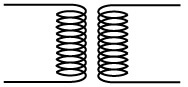
Step-up transformer
As the name specifies the secondary voltage is stepped up with a ratio compared to primary voltage. This is achieved by increasing the number of coil turns in the secondary as shown in figure.
In power plant this transformer is used as connecting transformer of Generator to Grid. I.e. the Generated to low voltage should be suitably stepped up to connect to high voltage grid.
Step-down transformer
In this transformer the voltage is stepped down at the secondary from high voltage primary so that it is called as step-down transformer. The winding turns will be high at primary side where as it will less at secondary side.
In power plant the use of this transformer are very high where the grid power supply stepped down and given to corresponding plant auxiliaries during starting of the power plant. Once the plant has started then the voltage stepping down is necessary where the plant auxiliaries will operate at low voltage compared to its generated voltage.
In distribution also the step down transformer is widely used to convert the high grid voltage to the low voltage which can be used at house purposes.
Transformer based on the core medium used
The transformers are divided as Air core and iron core under this classification. I.e. the medium placed between the primary and secondary air in air core type transformer and iron in iron core type transformer.
Air core transformer
The primary and secondary windings wounded on non magnetic strip where the flux linkage between primary and secondary is through the air. The mutual inductance effect is less in air core compared to iron core i.e. the reluctance offered to the generated flux is high in the air medium where as in the iron core it is less. But the hysteresis and eddy current losses which are dominant in iron core type are less or completely eliminated in air core type transformer.
Iron core transformer
The two windings are wounded on iron plates which provide a perfect linkage path to the generated flux. Due to the conductive or magnetic property of the iron it offers less reluctance to the linkage flux. These are widely used transformers in which is efficiency is high compared to air core type transformer.
Transformer based on winding arrangements
Auto Transformer
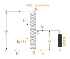
Normal transformers have two windings placed on two different sides i.e. primary and secondary but in auto transformer, the both the windings that is primary and secondary windings are connected to each other both physically and magnetically. There is one common winding which forms both primary and secondary winding in which voltage is varied by changing the position of secondary tapping on the body of the coil.
Transformer based on usage
The transformers are used to do many functions according to the necessarily. These are classified as power transformer, measuring transformer, protection transformer and distribution transformer.
Power Transformer
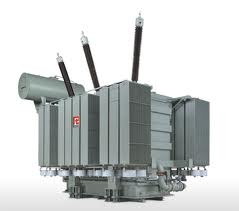
The power transformers are big in size and used for high power transfer applications, where the transmission voltage is greater than 33KV. It used in generating station and Transmission substation .high insulation level.
Distribution transformer
It is used for the distribution of electrical energy at low voltage as less than 33KV in industrial purpose and 440v-220v in domestic purpose. It work at low efficiency at 50-70%, small size, easy in installation, having low magnetic losses & it is not always fully loaded.
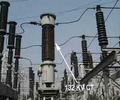
Measurement Transformer
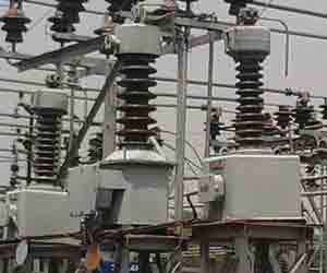
These are used to measure the some electrical quantity like voltage, current etc. As their name specifies these are classified as potential transformers, current transformers etc.
Protection transformers
These types of transformers are used in component protections. The major difference between measuring and protection transformers is the accuracy i.e. the protection transformers should be more accurate compared to measuring transformers.
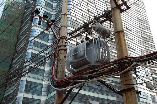
Transformers based on the place of use
These are classified as indoor and outdoor transformers. Indoor transformers are covered with proper roof like as in the process industry. The outdoor transformers are distribution type which are placed in substations etc.