Inst ToolsInst ToolsInst Tools
  • Courses
  • Automation
    • PLC
    • Control System
    • Safety System
    • Communication
    • Fire & Gas System
  • Instrumentation
    • Design
    • Pressure
    • Temperature
    • Flow
    • Level
    • Vibration
    • Analyzer
    • Control Valve
    • Switch
    • Calibration
    • Erection & Commissioning
  • Interview
    • Instrumentation
    • Electrical
    • Electronics
    • Practical
  • Q&A
    • Instrumentation
    • Control System
    • Electrical
    • Electronics
    • Analog Electronics
    • Digital Electronics
    • Power Electronics
    • Microprocessor
  • Request
Search
  • Books
  • Software
  • Projects
  • Process
  • Tools
  • Basics
  • Formula
  • Power Plant
  • Root Cause Analysis
  • Electrical Basics
  • Animation
  • Standards
  • 4-20 mA Course
  • Siemens PLC Course
Reading: Types of Cathodic Protection for Pipeline Protection
Share
Font ResizerAa
Inst ToolsInst Tools
Font ResizerAa
  • Courses
  • Design
  • PLC
  • Interview
  • Control System
Search
  • Courses
  • Automation
    • PLC
    • Control System
    • Safety System
    • Communication
    • Fire & Gas System
  • Instrumentation
    • Design
    • Pressure
    • Temperature
    • Flow
    • Level
    • Vibration
    • Analyzer
    • Control Valve
    • Switch
    • Calibration
    • Erection & Commissioning
  • Interview
    • Instrumentation
    • Electrical
    • Electronics
    • Practical
  • Q&A
    • Instrumentation
    • Control System
    • Electrical
    • Electronics
    • Analog Electronics
    • Digital Electronics
    • Power Electronics
    • Microprocessor
  • Request
Follow US
All rights reserved. Reproduction in whole or in part without written permission is prohibited.
Inst Tools > Blog > Control Systems > Types of Cathodic Protection for Pipeline Protection

Types of Cathodic Protection for Pipeline Protection

Last updated: October 26, 2019 1:28 pm
Editorial Staff
Control Systems
1 Comment
Share
6 Min Read
SHARE

Cathodic Protection

There are two general methods of cathodic protection,

Contents
Cathodic ProtectionGalvanic SystemImpressed Current SystemConnections
  1. the galvanic system and
  2. the impressed current system.

Galvanic System

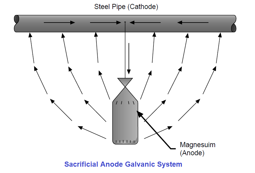
The galvanic system uses a sacrificial anode of a material having a higher potential on the electromotive series than the material to be protected (Fig. 1).

Sacrificial Anode Galvanic System

Fig: 1

Magnesium, zinc or aluminum are typical sacrificial anode materials. These anodes are designed to corrode and “sacrifice” themselves to protect the pipe, tank, etc. The anodes must be large enough to provide protection for a reasonable length of time before they are dissipated. Then they must be replaced for protection to continue.

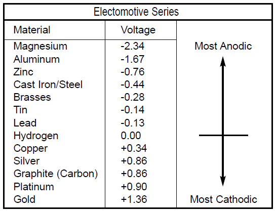
The electromotive series (Table 1) lists several materials from the most anodic, or most active, at the top of the list to the most cathodic, or least active, at the bottom of the list. Also listed is the voltage or potential of the materials in seawater in relation to hydrogen. Any material on the list will protect any material listed below it.

Cathodic Protection Anode and Cathode Materials

Table: 1

Impressed Current System

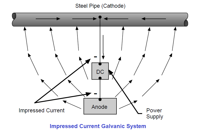
The impressed current system uses an outside source of electricity from a DC power supply, powered by solar, wind or the power company. This system uses a DC current of a magnitude greater than, and flowing in the opposite direction to, the natural galvanic cell current.

An anode is also required with the impressed current system but it can be of an inexpensive material such as scrap steel or graphite (Fig. 2). There is practically no limit on the current output in an impressed current system.

Impressed Current Galvanic System

Fig: 2

To conserve the current requirements for cathodic protection on a pipeline, normal installation practice calls for pipes to be coated to insulate the pipe from the corrosive environment. However, these coatings are never perfect and/or are damaged when the pipe is installed. The breaks in the coating (called holidays) are protected by the cathodic protection system. Since the amount of steel exposed at the holidays is very small compared to a bare pipeline, the amount of current required to protect the pipeline is reduced in a direct ratio.

To protect the pipeline in the case of stray current, the pipe must be bonded to the negative side of the DC power supply station with a low resistance conductor. This provides a direct metallic path for the return current to follow as it leaves the pipe (Fig. 3).

Protect the pipeline with Stray currents

Fig: 3

A few basic rules in designing a cathodic protection system include:

1. Bonding together of all structures (tanks, pipes, both across joints and between different pipes, etc.) is of absolute necessity for proper protection. This will provide a metallic return current path for any cathodic current.

2. A study is needed to determine any effect of the cathodic protection system on any “foreign” (owned by others) nearby structures. Any cathodic protection current picked up by a foreign structure must also leave that structure – which may cause corrosion.

Connections

Let us look at the electrical connections required in a cathodic protection system and why they are different than those required for a grounding system.

Cathodic connections are low current connections rather than grounding connections. Grounding connections are required to withstand damage while conducting huge surges of ground fault current. Cathodic protection connections are required to carry only a small but continuous current. Therefore cathodic protection connections do not have to be as massive as grounding connections.

A very low resistance system is required for a cathodic protection system, and it must remain low in resistance over the life of the system. The higher the resistance, the less efficient is the cathodic protection system. Cathodic Protection Connections meet this low resistance requirement, both when installed and over the life of the system.

The pipe used in transmission pipeline systems is usually a highly stressed thin wall steel pipe. Any connection to this pipe by the cathodic protection wires or the test leads must not damage the pipe. Cathodic Protection Connections use a special alloy weld metal developed to minimize the effect the weld has on the pipe. These connections have been proven by independent tests not to be detrimental to the pipe, and more than 45 years of usage without any detrimental effects have provided field proof to the tests.

Do you face any problems with cathodic protection? Share with us.

Reference: erico

Read Next:

  • Solve Ground Loop Problems
  • Identification of Equipment
  • Definition of Electrical Ground
  • Importance of Panel Grounding
  • Electrical Earthing or Grounding
Don't Miss Our Updates
Be the first to get exclusive content straight to your email.
We promise not to spam you. You can unsubscribe at any time.
Invalid email address
You've successfully subscribed !

Continue Reading

Interconnection between PLC, MCC, LCP & Pumps – Video
Instrumentation and Control Project Packages – Detail Engineering
Recognizing an Over-Tuned PID Controller by Phase Shift
Electrical Earthing Calculations
Difference Between Single Pair Ethernet and Traditional Ethernet
Label the Electrical Circuit Schematic
Share This Article
Facebook Whatsapp Whatsapp LinkedIn Copy Link
Share
1 Comment
  • Laura Gilsulate says:
    May 9, 2020 at 12:12 am

    Good to see these helpful information here,Thanks lots for sharing them with us.

    Reply

Leave a Reply Cancel reply

Your email address will not be published. Required fields are marked *

Stay Connected

128.3kFollowersLike
69.1kFollowersFollow
210kSubscribersSubscribe
38kFollowersFollow

Categories

Explore More

Integral Controller Principle
Control Systems Interview Questions & Answers
Workstation Healthiness Checks
Process Dynamics and PID Controller Tuning
DeltaV System Configuration Changes and Download
What is DCS? (Distributed Control System)
Fundamental Motion Control Commands
What is Multi-touch Technology? – Industrial Automation

Keep Learning

Basics of Motion Controllers

Basics of Motion Controllers

Control Valve Split Range Example - 2

Control Valve Split Range Example

Solve Pressure Control System Problems

Pressure Control System Problems

DCS Quiz

DCS Quiz

Instrumentation Cyber Security

Instrumentation Cyber Security Glossary

Compare DCS, PLC, RTU

Difference between DCS, PLC, and RTU ?

Emerson Smart Wireless gateway

Modbus Function Codes and Addresses

Ziegler-Nichols open-loop Tuning

Ziegler-Nichols Open-Loop Method

Learn More

Single Block and Bleed Valve Manifold

Single Block and Bleed Valve Manifold Operation

Troubleshooting Ultrasonic Flow Meter Common Problems

Troubleshooting Ultrasonic Flow Meter Common Problems

Pneumatic Control Mechanisms Objective Questions

Pneumatic Control Mechanisms Objective Questions

Bathtub curve

Bathtub Curve

noise-abatement trim

Control Valve Noise Problems

flow Nozzle

Flow Nozzle Principle, Advantages, Disadvantages, Applications

Pressure-sensing level transmitter

Moving Pressure Sensing Level Transmitter from Top to Bottom

Three phase inverter Animation

Three Phase Inverter Animation

Menu

  • About
  • Privacy Policy
  • Copyright

Quick Links

  • Learn PLC
  • Helping Hand
  • Part Time Job

YouTube Subscribe

Follow US
All rights reserved. Reproduction in whole or in part without written permission is prohibited.
Welcome Back!

Sign in to your account

Username or Email Address
Password

Lost your password?