Tap changing in Transformers
It is a normal fact that increase in load lead to decrease in the supply voltage. Hence the voltage supplied by the transformer to the load must be maintained within the prescribed limits. This can be done by changing the transformer turns ratio.
The taps are leads or connections provided at various points on the winding. The turns ratio differ from one tap to another and hence different voltages can be obtained at each tap.
Need for system voltage control
System voltage control is essential for:
1. Adjusting the terminal voltage of consumer within the prescribed limits
2. Adjustment of voltage based on change in load.
3. In order to control the real and reactive power.
4. For varying the secondary voltage based on the requirement.
Types of taps
Taps may be principal, positive or negative. Principal tap is one at which rated secondary voltage can be obtained for the rated primary voltage. As the name states positive and negative taps are those at which secondary voltage is more or less than the principle tap.
Taps are provided at the HV windings of the transformer because of the following reasons.
Taps are provided at the HV windings of the transformer because of the following reasons.
1. The number of turns in the High voltage winging is large and hence a fine voltage variation can be obtained.
2. The current on the low voltage winding of large transformers are high. Therefore interruption of high currents is a difficult task.
3. LV winding is placed nearer to the core and HV winding is placed outside. Therefore providing taps on the HV winding is comparatively easier than that of the LV winding.
Location of Taps
The taps can be provided at the phase ends, at the neutral point, or in the middle of the winding. The number of bushing insulators can be reduced by providing taps at the phase ends. When the taps are provided at the neutral point the insulation between various parts will be reduced. This arrangement is economical particularly important for the large transformer.
Tap changing methods
Tap changing causes change in leakage reactance, core loss, copper loss and perhaps some problems in the parallel operation of dissimilar transformer. There are two methods of tap changing.
1. Off load tap changing
2. On load tap changing
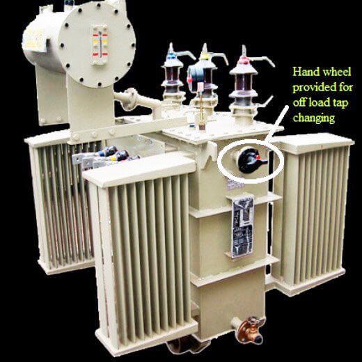
1. Off load (No load or off circuit) tap changing
2. On load tap changing
Procedure
Consider a high speed resistor type on load tap changers provided at neutral end of each phase as shown. The load is now supplied from the tap 1. The selector switches 1 and 2 are in contact with the taps 1 and 2. Now to switch over to the tap 2, the selector switch follows the following steps:
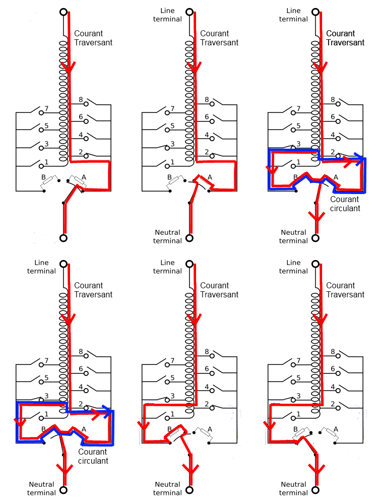
1. Contacts a and b are closed. The load current flows from tap 1 through contact b.
2. The external mechanism moves the diverter switch S3 from b, now load is supplied from contact a through resistor R1.
3. When diverter switch moves further it closes the contact d and both R1 and R2 are connected across taps 1 and 2 and the load current flows through these resistances to its mid point.
4. When S3 moves further to the left, contact a is opened and the load current flows from tap 2 through resistor R2 and d.
5. Finally the contact reaches the contact c and resistor R2 is short circuited. The load current flows from tap 2 through contact c.
Now to change the tap from 2 to 3, the selector switch S1 is first moved to tap 3 and the above steps are reverse. In order to limit the power loss it is necessary that the transformers are kept in the circuit for as minimum time as possible.
More compact tap changers with high reliability and performance are being made by employing vacuum switches in the diverter switch.







Very use full information
How do you know that the contact of your tap changer is defective on a power transformer
We can check by oil in OLTC