Inst ToolsInst ToolsInst Tools
  • Courses
  • Videos
  • Q & A
    • Interview
      • Instrumentation
      • Electronics
      • Electrical
      • Practical Questions
    • MCQ
      • Instrumentation MCQ
      • Electrical MCQ
      • Electronics MCQ
      • Control Systems MCQ
      • Analog Electronics MCQ
      • Digital Electronics MCQ
      • Power Electronics MCQ
      • Microprocessor MCQ
      • Multiple Choice Questions
  • EE
    • Electronics
      • Electronics Q & A
      • Electronic Basics
      • Electronic Devices & Circuits
      • Electronics Animation
      • Digital Electronics
    • Electrical
      • Electrical Basics
      • Electrical Q & A
      • Power Electronics
      • Electrical Machines
      • Electrical Animation
      • Power Systems
      • Switchgear & Protection
      • Transmission & Distribution
  • Measure
    • Control Valves
    • Calibration
    • Temperature
    • Pressure
    • Flow
    • Level
    • Analyzers
    • Switches
    • Vibration
    • Solenoid Valve
  • Control
    • PLC Tutorials
    • Control Systems
    • Safety Instrumented System (SIS)
    • Communication
    • Fire & Gas System
  • More
    • Design
    • Tools
    • Animation
    • Basics
    • Formulas
    • Standards
    • TextBooks
    • Common
    • Software
    • Excel Tools
    • Erection & Commissioning
    • Process Fundamentals
    • Videos
    • Books
Search
All rights reserved. Reproduction in whole or in part without written permission is prohibited.
Reading: Transformer Tap Changing Working Principle
Share
Notification Show More
Font ResizerAa
Inst ToolsInst Tools
Font ResizerAa
  • Courses
  • PLC Tutorials
  • Control Systems
Search
  • Courses
  • Videos
  • Q & A
    • Interview
    • MCQ
  • EE
    • Electronics
    • Electrical
  • Measure
    • Control Valves
    • Calibration
    • Temperature
    • Pressure
    • Flow
    • Level
    • Analyzers
    • Switches
    • Vibration
    • Solenoid Valve
  • Control
    • PLC Tutorials
    • Control Systems
    • Safety Instrumented System (SIS)
    • Communication
    • Fire & Gas System
  • More
    • Design
    • Tools
    • Animation
    • Basics
    • Formulas
    • Standards
    • TextBooks
    • Common
    • Software
    • Excel Tools
    • Erection & Commissioning
    • Process Fundamentals
    • Videos
    • Books
Follow US
All rights reserved. Reproduction in whole or in part without written permission is prohibited.
Inst Tools > Blog > Electrical Machines > Transformer Tap Changing Working Principle

Transformer Tap Changing Working Principle

Last updated: September 17, 2016 4:02 pm
Editorial Staff
Electrical Machines
3 Comments
Share
8 Min Read
SHARE

Tap changing in Transformers

It is a normal fact that increase in load lead to decrease in the supply voltage. Hence the voltage supplied by the transformer to the load must be maintained within the prescribed limits. This can be done by changing the transformer turns ratio.

The taps are leads or connections provided at various points on the winding. The turns ratio differ from one tap to another and hence different voltages can be obtained at each tap.

Need for system voltage control

System voltage control is essential for:

1. Adjusting the terminal voltage of consumer within the prescribed limits

2. Adjustment of voltage based on change in load.

3. In order to control the real and reactive power.

4. For varying the secondary voltage based on the requirement.

Types of taps

Taps may be principal, positive or negative. Principal tap is one at which rated secondary voltage can be obtained for the rated primary voltage. As the name states positive and negative taps are those at which secondary voltage is more or less than the principle tap.

Taps are provided at the HV windings of the transformer because of the following reasons.

Taps are provided at the HV windings of the transformer because of the following reasons.

1. The number of turns in the High voltage winging is large and hence a fine voltage variation can be obtained.

2. The current on the low voltage winding of large transformers are high. Therefore interruption of high currents is a difficult task.

3. LV winding is placed nearer to the core and HV winding is placed outside. Therefore providing taps on the HV winding is comparatively easier than that of the LV winding.

Location of Taps

The taps can be provided at the phase ends, at the neutral point, or in the middle of the winding. The number of bushing insulators can be reduced by providing taps at the phase ends. When the taps are provided at the neutral point the insulation between various parts will be reduced. This arrangement is economical particularly important for the large transformer.

Tap changing methods

Tap changing causes change in leakage reactance, core loss, copper loss and perhaps some problems in the parallel operation of dissimilar transformer. There are two methods of tap changing.

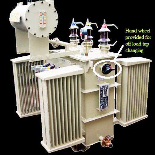
1. Off load tap changing

2. On load tap changing

1. Off load (No load or off circuit) tap changing

As the name indicates, in this method tap changing is done after disconnecting the load from the transformer. Off load tap changing is normally provided in low power, low voltage transformers. It is the cheapest method of tap changing. The tap changing is done manually though hand wheel provided in the cover. In some transformers arrangements to change the taps by simply operating the mechanical switches are also provided.
Off load Tap Changer Principle
The winding is tapped at various points. Since the taps are provided at various points in the winding single tap must be connected at a time otherwise it will lead to short circuit. Hence the selector switch is operated after disconnecting the load.To prevent unauthorized operation of an off load tap changer, mechanical lock is provided. To prevent inadvertent operation, electromechanical latching devices are provided to operate the circuit breakers and de-energize the transformer as soon as the tap changer handle is moved.

2. On load tap changing

On load tap changers are used to change the turns ratio without disconnecting the load from it. Tap changing can be done even when the transformer is delivering load. On load tap changers considerable increases the efficiency of the system. Nowadays almost all the large power transformers are provided with on load tap changers.The reason for providing On load tap changer in power transformers are1. During the operation of on load tap changers the main circuit remains unaffected.2. Dangerous sparking is prevented.The taps on the windings are brought to a separate oil filled compartment in which the on load tap changer switch is housed. The tap changer is a form of mechanical selector switch which is operated by a motor by local or remote control.
A handle fitted for manual operation in case of emergency.The selector switch is a form of make before break switch and during the transition of the tap changers from one tap to another, momentary connection must be made between the adjacent taps. This results in short circuit between the adjacent taps. The short circuit current must be limited by including resistor or reactor. Hence all forms of on load tap changer are provided with an impedance to limit short circuit current during tap changing operation. The impedance may be resistance or a center tapped reactance. In modern designs it is invariably carried out by a pair of resistors.

Procedure

Consider a high speed resistor type on load tap changers provided at neutral end of each phase as shown. The load is now supplied from the tap 1. The selector switches 1 and 2 are in contact with the taps 1 and 2. Now to switch over to the tap 2, the selector switch follows the following steps:

Tap changing switch Animation

1. Contacts a and b are closed. The load current flows from tap 1 through contact b.

2. The external mechanism moves the diverter switch S3 from b, now load is supplied from contact a through resistor R1.

3. When diverter switch moves further it closes the contact d and both R1 and R2 are connected across taps 1 and 2 and the load current flows through these resistances to its mid point.

4. When S3 moves further to the left, contact a is opened and the load current flows from tap 2 through resistor R2 and d.

5. Finally the contact reaches the contact c and resistor R2 is short circuited. The load current flows from tap 2 through contact c.

Now to change the tap from 2 to 3, the selector switch S1 is first moved to tap 3 and the above steps are reverse. In order to limit the power loss it is necessary that the transformers are kept in the circuit for as minimum time as possible.

More compact tap changers with high reliability and performance are being made by employing vacuum switches in the diverter switch.

Don't Miss Our Updates
Be the first to get exclusive content straight to your email.
We promise not to spam you. You can unsubscribe at any time.
Invalid email address
You've successfully subscribed !

Continue Reading

Synchronous Motor Working Principle
Induction Motors Faults and Protection
AC Motor Braking
Transformer Open and Short Circuit Tests
Losses in a DC Generator
Faults in a Transformer
Share This Article
Facebook Whatsapp Whatsapp LinkedIn Copy Link
Share
3 Comments
  • Noor Mustafa says:
    September 17, 2016 at 4:56 pm

    Very use full information

    Reply
  • Okuta G Otunuya says:
    September 5, 2022 at 1:27 pm

    How do you know that the contact of your tap changer is defective on a power transformer

    Reply
    • T says:
      October 31, 2023 at 2:14 pm

      We can check by oil in OLTC

      Reply

Leave a Reply Cancel reply

Your email address will not be published. Required fields are marked *

Stay Connected

128.3kFollowersLike
69.1kFollowersFollow
208kSubscribersSubscribe
38kFollowersFollow

Categories

Explore More

Why Damper windings used in synchronous motors
DC Motor Speed Control
Why rating of Synchronous Generators and Alternators in MVA or KVA
DC Motor Applications in Industries
Advantages and Applications of zigzag transformer
Advantages and Disadvantages of Squirrel Cage Induction motor
Advantages and Disadvantages of Slip Ring Induction Motor
Parallel Operation of Alternators
Why Starting Current of Induction Motor is High
AC Motor Speed Control

Keep Learning

Differences Between AC and DC Motors

Why Armature is placed on Stator for Synchronous machines

Electrical Machines Objective Questions

Electrical Machines Objective Questions

Advantages & Disadvantages of Variable Speed Drives

Difference between Induction motor and Synchronous motor

Use of line reactors

Use of line reactors

Motor Star Delta Connections

How Motor Star Delta Starter Works ?

Synchronous Motor Is Not Self Starting?

Discover More

NDIR gas analysis

Non-Dispersive Analyzers

Nuclear Magnetic Resonance Spectrometer Questions and Answers

Nuclear Magnetic Resonance Spectrometer Questions & Answers

Closed-Tank-DP-Type-Level-Measurement-with-wet-leg-and-transmitter-installed-below-tapping-point

Level Measurement with Wet leg and Installed Below Tapping Point

Capillary Remote Seal Leave Measurement

Siemens Pressure Transmitter with Remote Seals Calculations

Control Valve Tips and Tricks

Control Valve Tips and Tricks

ATEX Ratings, Intrinsic Safety, Hazardous Areas and Explosive Atmospheres

ATEX Ratings, Intrinsic Safety, Hazardous Areas and Explosive Atmospheres

Top Beginner Soldering Mistakes

Top Beginner Soldering Mistakes and How to Avoid Them?

Methods of Transistor Biasing

Methods of Transistor Biasing

Follow US
All rights reserved. Reproduction in whole or in part without written permission is prohibited.
Welcome Back!

Sign in to your account

Username or Email Address
Password

Lost your password?