We conduct open circuit and short circuit test on single phase transformer to determine the efficiency and regulation of a transformer on any load condition and at any power factor.Open circuit & short circuit test are also called as OC test & SC test on transformer.This method of finding the parameters of a transformer is called as an indirect loading method.
Open Circuit(OC) and Short Circuit(SC) Test on Transformer
What is the need of OC & SC test on transformers?
Open circuit test and short circuit test on transformer are very economical and convenient because they are performed without actually loading of the transformer.because they furnish the required information without actually loading the transformer. In fact, the testing of very large a.c. machinery consists of running two tests similar to the open and short-circuit tests of a transformer.
Open-circuit or No-load Test On Single Phase Transformers
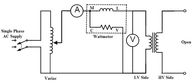
The circuit diagram for open circuit test is shown in the figure. A voltmeter(V), wattmeter(W), and an ammeter(A) are connected in LV side of the transformer.Usually high voltage (HV) winding is kept open and the low voltage (LV) winding is connected to its normal supply.Because we are going to find the max output voltage of transformer which is present at HV side.This is the reason why HV winding is open circuited.
Procedure of Open Circuit(OC) Test
- Switch on single phase AC supply,with the help of variac, increase the voltage until the voltmeter raeds the rated voltage of the LV side.
- At theinstant of rated LV voltage, Note down the readings of all three instruments.(Voltmeter, Ammeter and Wattmeter readings) are recorded.
The ammeter reading gives the no load current I0.As no load current (I0) very small,voltage drop due to this current also neglected.The input power supplied to the transformer is indicated by the watt meter (W).Output power of transformer in open circuit test is zero because other side of transformer is open circuited.That means input supply is to just compensate the core losses and copper losses.By neglecting some voltage drop due to small no-load current,Watt meter (W) reading gives the core losses of the transformer.
Here,Wo = Pi = Iron losses
Calculations : We know that,
Wo = VoIo cos Φ(watt meter reading)
cos Φo = Wo /(VoIo) = no load power factor
Once cos Φo is known we can obtain,
Ic = Io cos Φo
and Im = Io sin Φo
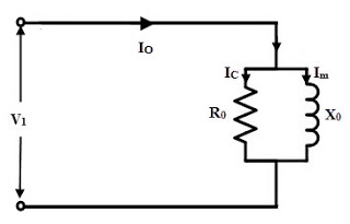
Once Ic and Im are known we can determine exciting circuit parameters as,
Ro = Vo /Ic Ω
Xo = Vo /Im Ω
where,
X0,R0 are equivalent exciting reactance,resistance of transformer.
Key Point : We should use LPF (low power factor)watt meter to get error free results.Beacuse cos Φo is very low in the above case.The above values are calculated by taking LV side of transformer as reference.If the meters are connected on secondary and primary is kept open then from O.C. test we get Ro’ and Xo’ with which we can obtain Ro and Xo knowing the transformation ratio K.
The equivalent circuit derived by the OC test is shown below.
Hence,we can conclude that open circuit test on transformer gives gives core losses of transformer and shunt parameters of the equivalent circuit.
Short Circuit Or Impedance Test On Transformer
The connection diagram for short circuit test on transformer is shown in the figure. A voltmeter(V), wattmeter(W), and an ammeter(A) are connected in HV side of the transformer as shown.The secondary winding is short circuited with the help of thick copper wire or solid link. As high voltage side is always low current side, it is convenient to connect high voltage side to supply and shorting the low voltage side.
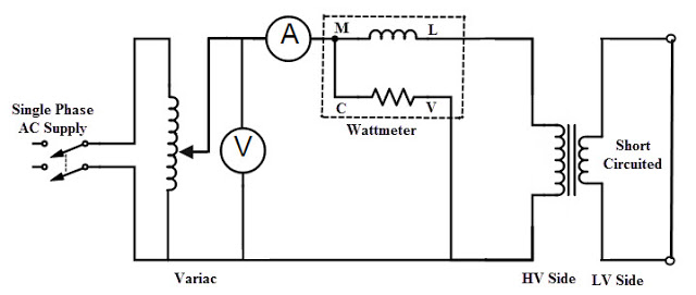
Procedure of Short Circuit(OC) Test
- Apply voltage to HV side.
- Increase the voltage from the zero until the ammeter reading equals the rated current.
- At the instant of rated HV current, Note down the readings of all three instruments.(Voltmeter, Ammeter and wattmeter readings) are recorded.
Now the current flowing through the windings of transformer is rated current. Hence the total copper loss will be full load copper loss.Iron losses are neglected due to small fraction of voltage supllied. Hence the wattmeter reading shows the power loss which is equal to full load copper losses as iron losses are neglected.
Wsc = (Pcu) F.L. = Full load copper loss
Calculations : From S.C. test readings we can write,
Wsc = Vsc Isc cos Φsc
... cos Φsc = Vsc Isc /Wsc = short circuit power factor
Wsc = Isc2 R1e = copper loss
... R1e =Wsc /Isc2
while Z1e =Vsc /Isc = √(R1e2 + X1e2)
X1e = √(Z1e2 – R1e2)
Thus we get the equivalent circuit parameters R1e, X1e and Z1e. Knowing the transformation ratio K, the equivalent circuit parameters referred to secondary also can be obtained.
Calculation of Efficiency of transformer from O.C. and S.C. Tests
Efficiency, η = Power output in KW/ Power input in KW
= Power output in KW/ (Power output in KW + Losses)
= Power output in KW/ (Power output in KW + Copper loss + Core loss)
Consider that the KVA rating of the transformer is S, a fraction of the load is x and the power factor of the load is Cos Φ. Then
The output power in KW = xSCos Φ
Suppose the copper loss at full load is Pcu (since x =1),
Then copper loss at x per unit loading = x2Pcu
Therefore the efficiency of the transformer is
Efficiency, η = xSCos Φ / (xS Cos Φ + x2 Pxcu + Pxcore)
In the above efficiency equation, the core or iron losses and full load copper losses are found by OC and SC tests.
Calculation of Regulation
Percentage voltage regulation, %R = ((E2 – V2)/ V2 )×100
The expression of voltage regulation in terms voltage drops is given as
%R = ((I1R01 cos Φ +/- I1X01 sin Φ) / V1) ×100
Or
%R = ((I2R02 cos Φ +/- I2X02 sin Φ) / V2) ×100
The above two equations are used based on the parameters are referred to primary or secondary sides. Hence, from the SC test data we can find out the regulation of a transformer. The positive sign is used for lagging power factor and negative sign is used for leading power factor.