Circuits consisting of just one battery and one load resistance are very simple to analyze, but they are not often found in practical applications. Usually, we find circuits where more than two components are connected together.
There are two basic ways in which to connect more than two circuit components:
First, an example of a series circuit:
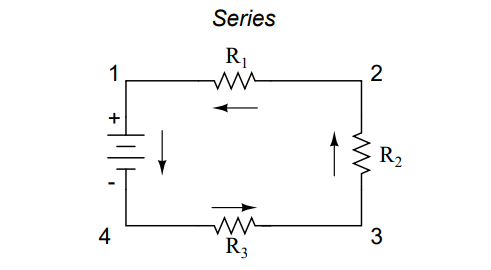
Here, we have three resistors (labeled R1, R2, and R3), connected in a long chain from one terminal of the battery to the other. (It should be noted that the subscript labeling – those little numbers to the lower-right of the letter ”R” – are unrelated to the resistor values in ohms. They serve only to identify one resistor from another.)
The defining characteristic of a series circuit is that there is only one path for electrons to flow. In this circuit the electrons flow in a counter-clockwise direction, from point 4 to point 3 to point 2 to point 1 and back around to 4.
Now, let’s look at the other type of circuit, a parallel configuration:
Again, we have three resistors, but this time they form more than one continuous path for electrons to flow. There’s one path from 8 to 7 to 2 to 1 and back to 8 again. There’s another from 8 to 7 to 6 to 3 to 2 to 1 and back to 8 again. And then there’s a third path from 8 to 7 to 6 to 5 to 4 to 3 to 2 to 1 and back to 8 again. Each individual path (through R1, R2, and R3) is called a branch.
The defining characteristic of a parallel circuit is that all components are connected between the same set of electrically common points. Looking at the schematic diagram, we see that points 1, 2, 3, and 4 are all electrically common. So are points 8, 7, 6, and 5. Note that all resistors as well as the battery are connected between these two sets of points.A
And, of course, the complexity doesn’t stop at simple series and parallel either!
We can have circuits that are a combination of series and parallel, too:
In this circuit, we have two loops for electrons to flow through: one from 6 to 5 to 2 to 1 and back to 6 again, and another from 6 to 5 to 4 to 3 to 2 to 1 and back to 6 again.
Notice how both current paths go through R1 (from point 2 to point 1). In this configuration, we’d say that R2 and R3 are in parallel with each other, while R1 is in series with the parallel combination of R2 and R3.
This is just a preview of things to come. Don’t worry! We’ll explore all these circuit configurations in detail, one at a time!
The basic idea of a ”series” connection is that components are connected end-to-end in a line to form a single path for electrons to flow:
The basic idea of a ”parallel” connection, on the other hand, is that all components are connected across each other’s leads. In a purely parallel circuit, there are never more than two sets of electrically common points, no matter how many components are connected. There are many paths for electrons to flow, but only one voltage across all components:
Series and parallel resistor configurations have very different electrical properties. We’ll explore the properties of each configuration in the sections to come.
Initially, AC motors were constructed like DC motors. Numerous problems were encountered due to changing…
Learn about the AC Instrumentation Transducers like Potentiometer, LVDT, RVDT, Synchro, and Capacitive Transducers.
AC bridge circuit unknown impedance is balanced by a standard impedance of similar type on…
Power Quality is the general term given to represent an AC power system freedom from harmonic…
Hall effect - Voltage is proportional to current and strength of the perpendicular magnetic field.…
Learn about the Frequency and Phase Measurement from our free online electronics and electrical engineering…


