Thermocouples and RTDs are the most common sensors used in process temperature measurements.
Simulating a process sensor signal into a process instrument or control system input enables a technician to verify whether the device responds correctly to the temperature measured by the instrument.
There are many different ways to simulate these sensors for testing purposes.
You can use a mV dc source and a mV vs temperature look up table for simulating thermocouples or a resistance decade box and resistance vs temperature look up table for simulating RTDs.
This method, however, has become outdated with modern temperature calibrators that do the conversion for the user.
With modern calibrators, simply select the sensor type to simulate, input the temperature to source and connect to the devices under test.

To perform the test:
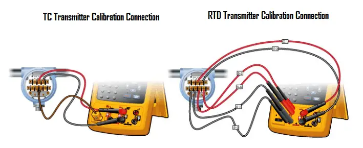
To use a thermocouple simulator to test a device with a thermocouple input:
To use an RTD simulator to test a device with an RTD input:
Article source: Fluke
The PLC panel and MCC panel interface signals are start, stop, run feedback, trip, local…
In this article, we are going to discuss about shutter door control using induction motor…
Electrical Drives control the motion of electric motors. Motion control is required in industrial and…
PLC ladder logic design to control 3 motors with toggle switch and explain the program…
VFD simulator download: Master the online tool from the Yaskawa V1000 & programming software for…
The conveyor sorting machine is widely used in the packing industries using the PLC program…
View Comments
Difference between grounding and ungrounding thermocouple ?
Grouded = fastest response.