Skip to content
  • About
  • Contact
  • Disclaimer
  • Copyright
  • Subscribe
  • Submit Articles
  • Forum
  • Helping Hand
  • Part Time Job
  • Learn PLC
  • Game
  • Donate
  • Videos
Inst Tools
  • Ask
  • Courses
  • Videos
  • Q & A
    • Interview
      • Instrumentation
      • Electronics
      • Electrical
      • Practical Questions
    • MCQ
      • Instrumentation MCQ
      • Electrical MCQ
      • Electronics MCQ
      • Control Systems MCQ
      • Analog Electronics MCQ
      • Digital Electronics MCQ
      • Power Electronics MCQ
      • Microprocessor MCQ
      • Multiple Choice Questions
  • EE
    • Electronics
      • Electronics Q & A
      • Electronic Basics
      • Electronic Devices & Circuits
      • Electronics Animation
      • Digital Electronics
    • Electrical
      • Electrical Basics
      • Electrical Q & A
      • Power Electronics
      • Electrical Machines
      • Electrical Animation
      • Power Systems
      • Switchgear & Protection
      • Transmission & Distribution
  • Measure
    • Control Valves
    • Calibration
    • Temperature
    • Pressure
    • Flow
    • Level
    • Analyzers
    • Switches
    • Vibration
    • Solenoid Valve
  • Control
    • PLC Tutorials
    • Control Systems
    • Safety Instrumented System (SIS)
    • Communication
    • Fire & Gas System
  • More
    • Design
    • Tools
    • Animation
    • Basics
    • Formulas
    • Standards
    • TextBooks
    • Common
    • Software
    • Excel Tools
    • Erection & Commissioning
    • Process Fundamentals
    • Videos
    • Books

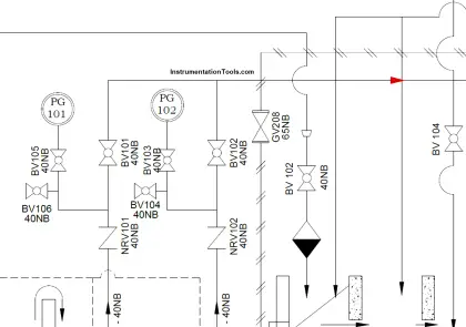
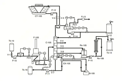
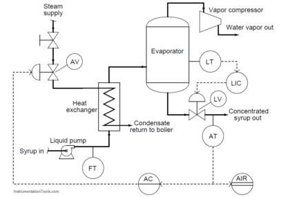
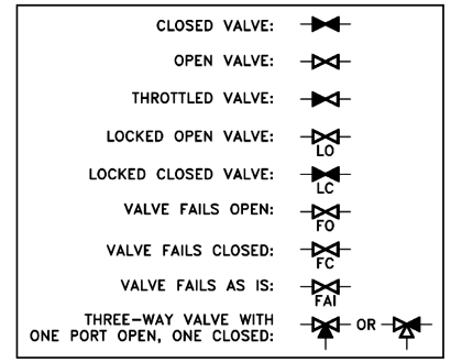
piping and instrumentation drawing

P&ID Legend

What is a Legend? – Piping and Instrumentation Diagram

A legend is a column that denotes symbols of various types of instruments in a piping and instrumentation diagram (P&ID).

Piping and Instrument Drawing

Difference between PFD and P&ID with Example

Process drawings are divided into two major categories. Process Flow diagrams (PFD) and Piping and Instrumentation diagrams (P&ID).

Questions on Piping and Instrumentation Diagrams

Questions on Piping and Instrumentation Diagrams

In this post, we shared the 12 Questions on Piping and Instrumentation Diagrams related to the steam heat exchanger level

P & ID Valve Status Symbols

Piping and Instrumentation Drawing (P&ID) Tutorials – Part 4

Reading Engineering P&IDs Standards and conventions have been developed to provide consistency from drawing to drawing. To accurately interpret a

Pneumatic Level Control Valve

Piping and Instrumentation Drawing (P&ID) Tutorials – Part 3

To read and understand engineering fluid diagrams and prints, usually referred to as P&IDs, an individual must be familiar with

Isometric Projection

Piping and Instrumentation Drawing (P&ID) Tutorials – Part 2

To read a drawing correctly, the user must have a basic understanding of the various categories of drawings and the

Plant Engineering Drawings

Piping and Instrumentation Drawing (P&ID) Tutorials – Part 1

A through knowledge of the information presented in the title block, the revision block, the notes and legend, and the

FOLLOW US

Categories

Recent Comments

  • UMAKANTA MOHANTA on RTD Calibration
  • MD SHAHBAZ ALI on Differential Pressure Transmitter Calibration Procedure
  • rohit on Anti-static Wrist Straps in Industrial Automation
  • zhangwenfei on Gas and Liquid Measurement: Processes and Solutions for the Industrial Sector
  • Troy Anthony Knowles on Free Instrumentation Course for Trainee Engineers
  • Rotimi Adeyeye on PLC Electric Motor Interlocks
  • Rubén Miguel on Formulas to calculate mA from PV, LRV and URV
2025 © Reproduction without explicit permission is prohibited. - PLC SCADA Courses - Engineers Community