Skip to content
  • About
  • Contact
  • Disclaimer
  • Copyright
  • Subscribe
  • Submit Articles
  • Forum
  • Helping Hand
  • Part Time Job
  • Learn PLC
  • Game
  • Donate
  • Youtube

Inst Tools

  • Courses
  • Videos
  • Q & A
    • Interview
      • Instrumentation
      • Electronics
      • Electrical
      • Practical Questions
    • MCQ
      • Instrumentation MCQ
      • Electrical MCQ
      • Electronics MCQ
      • Control Systems MCQ
      • Analog Electronics MCQ
      • Digital Electronics MCQ
      • Power Electronics MCQ
      • Microprocessor MCQ
      • Multiple Choice Questions
  • EE
    • Electronics
      • Electronics Q & A
      • Electronic Basics
      • Electronic Devices & Circuits
      • Electronics Animation
      • Digital Electronics
    • Electrical
      • Electrical Basics
      • Electrical Q & A
      • Power Electronics
      • Electrical Machines
      • Electrical Animation
      • Power Systems
      • Switchgear & Protection
      • Transmission & Distribution
  • Measure
    • Control Valves
    • Calibration
    • Temperature
    • Pressure
    • Flow
    • Level
    • Analyzers
    • Switches
    • Vibration
    • Solenoid Valve
  • Control
    • PLC Tutorials
    • Control Systems
    • Safety Instrumented System (SIS)
    • Communication
    • Fire & Gas System
  • More
    • Design
    • Inst Forum
    • Tools
    • Animation
    • Basics
    • Formulas
    • Standards
    • TextBooks
    • Common
    • Software
    • Excel Tools
    • Erection & Commissioning
    • Process Fundamentals
    • Videos
    • Books

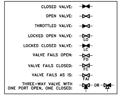
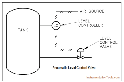
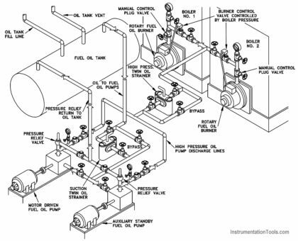
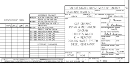
How to read Piping and Instrumentation Diagram

P & ID Valve Status Symbols

Piping and Instrumentation Drawing (P&ID) Tutorials – Part 4

Reading Engineering P&IDs Standards and conventions have been developed to provide consistency from drawing to drawing. To accurately interpret a

Pneumatic Level Control Valve

Piping and Instrumentation Drawing (P&ID) Tutorials – Part 3

To read and understand engineering fluid diagrams and prints, usually referred to as P&IDs, an individual must be familiar with

Isometric Projection

Piping and Instrumentation Drawing (P&ID) Tutorials – Part 2

To read a drawing correctly, the user must have a basic understanding of the various categories of drawings and the

Plant Engineering Drawings

Piping and Instrumentation Drawing (P&ID) Tutorials – Part 1

A through knowledge of the information presented in the title block, the revision block, the notes and legend, and the

Piping and Instrumentation Diagram

What is Piping and Instrumentation Diagram (P&ID) ?

Piping and Instrumentation Diagram (P&ID) is a drawing elaborating the details of piping and instrumentation of a processing plant, developed

Categories

Recent Comments

  • Ahmed Morsy on Difference Between RCCB and MCCB
  • Manoj on Opposite Acting Control Valves Application using PLC Ladder Logic
  • Muhammad Wasay Zia on Modbus Communication between Delta PLC with VFD
  • Ravi Shankar on Modbus Communication between Delta PLC with VFD
  • George Achakpo on Venturi Flow Meter Working Principle Animation
  • Mohammed Shakhawan on Gap Voltage of Bently Nevada Vibration Probe
  • Ravindra Angal on Free Download Programmable Logic Controller (PLC) Book
2023 © Reproduction without explicit permission is prohibited. - PLC SCADA Courses - Engineers Community
Don't Miss Our Updates
Be the first to get exclusive content straight to your email.
We promise not to spam you. You can unsubscribe at any time.
Invalid email address
You've successfully subscribed !
x
x