Inst ToolsInst ToolsInst Tools
  • Courses
  • Automation
    • PLC
    • Control System
    • Safety System
    • Communication
    • Fire & Gas System
  • Instrumentation
    • Design
    • Pressure
    • Temperature
    • Flow
    • Level
    • Vibration
    • Analyzer
    • Control Valve
    • Switch
    • Calibration
    • Erection & Commissioning
  • Interview
    • Instrumentation
    • Electrical
    • Electronics
    • Practical
  • Q&A
    • Instrumentation
    • Control System
    • Electrical
    • Electronics
    • Analog Electronics
    • Digital Electronics
    • Power Electronics
    • Microprocessor
  • Request
Search
  • Books
  • Software
  • Projects
  • Process
  • Tools
  • Basics
  • Formula
  • Power Plant
  • Root Cause Analysis
  • Electrical Basics
  • Animation
  • Standards
  • 4-20 mA Course
  • Siemens PLC Course
Reading: Silicon Carbide Lightning Arresters Working Principle
Share
Font ResizerAa
Inst ToolsInst Tools
Font ResizerAa
  • Courses
  • Design
  • PLC
  • Interview
  • Control System
Search
  • Courses
  • Automation
    • PLC
    • Control System
    • Safety System
    • Communication
    • Fire & Gas System
  • Instrumentation
    • Design
    • Pressure
    • Temperature
    • Flow
    • Level
    • Vibration
    • Analyzer
    • Control Valve
    • Switch
    • Calibration
    • Erection & Commissioning
  • Interview
    • Instrumentation
    • Electrical
    • Electronics
    • Practical
  • Q&A
    • Instrumentation
    • Control System
    • Electrical
    • Electronics
    • Analog Electronics
    • Digital Electronics
    • Power Electronics
    • Microprocessor
  • Request
Follow US
All rights reserved. Reproduction in whole or in part without written permission is prohibited.
Inst Tools > Blog > Power Systems > Silicon Carbide Lightning Arresters Working Principle

Silicon Carbide Lightning Arresters Working Principle

Last updated: January 1, 2016 8:58 am
Editorial Staff
Power Systems
No Comments
Share
4 Min Read
SHARE

Silicon Carbide Arresters (SIC):

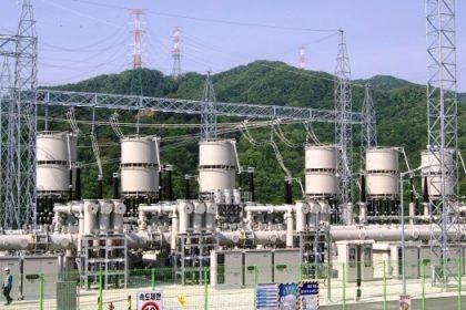
The Non linear lightning arrester basically consists of set of spark gaps in series with the silicon carbide non linear resistor elements. Lightning arresters are connected between the phase conductors and ground. During normal system operating voltage conditions, the spark gaps are non conducting and isolate the high tension (HT) conductors from the ground. However whenever an overvoltge of magnitude dangerous to the insulationSilicon Carbide (SIC) Arresters Working of the apparatus protected occurs ( these over voltages or over surges may be caused due to lightning strikes on the conductors or due to Extra High Voltage (EHV) switching) the spark gap breaks down and allows the high voltage surge current to flow through the ground.

Working Principle of Silicon Carbide (SIC) Lightning Arresters:

The volt-ampere characteristics of the non linear resistor in the lignting arrester can be approximately described by expression V = KIβ. Where K and β are dependent on the composition and manufacturing process of the Non linear Resistor (NLR). The value of β lies generally in the range of 0.3 and 0.45 for modern silicon carbide (SIC) lightning arresters. If the voltage across the Non Linear Resistor (NLR) doubles, the current would increase approximately by 10 times

Therefore, with multiple spark gaps arresters can withstand high Rate of Recovery Voltage (RRRV). The non-uniform voltage distribution between the gaps (which are in series in lightning arresters) presents a problem. To overcome this, capacitors and non-linear resistors are connected in parallel across each gap. In case of lightning arresters employed for high voltage applications, capacitors and nonlinear resistors are connected across the stock of gaps and NLRs. With the steep voltage wave surge the voltage is mainly controlled by the capacitor and at the power frequency by the non-linear resistors. It is obvious that when the over voltages cause the break down of the series gaps, the current would be very high so as to make the voltage to subside very fast. The highest voltage that appear across the lightning arrester would be either the spark over voltage of the arrester or thevoltage developed across the non-linear resistor during the flow of surge current. The lowest spark over voltage of the arrester is called the hundred percent impulse spark over voltage of the arrester. The voltage developed across the non-linear resistor during the flow of surge current is called residual voltage. The lower the value of the voltage developed the better the protection of the lightning arrester

Disadvantages of Silicon Carbide (SIC) Arresters:

Some of the disadvantages of silicon carbide arresters compared to gapless arresters are given below:

  • Silicon Carbide (SIC) arresters have inferior V-I Characteristics compared to Zno arresters (Metal oxide arresters).
  • Decrease in energy absorption (surge wave) capability compared to Zno arresters.
  • Probability of sparking between the gaps.

Advantages of Silicon Carbide (SIC) Arrester :

  • Due to the presence of gaps the normal power frequency voltage during normal operation is negligibly less compared to gap less arresters. Hence no leakage current flow between the line and earth in SIC arresters
Don't Miss Our Updates
Be the first to get exclusive content straight to your email.
We promise not to spam you. You can unsubscribe at any time.
Invalid email address
You've successfully subscribed !

Continue Reading

Corona Ring on Surge Arresters and other EHV equipment
Harmonics effect on Transformer
Why Symmetrical Components Used for Unbalanced faults in Power System
Harmonics effect on Induction Motor
Harmonics Disadvantages in Power System
Current Limiting Reactors and Short Circuit Currents
Share This Article
Facebook Whatsapp Whatsapp LinkedIn Copy Link
Share
Leave a Comment

Leave a Reply Cancel reply

Your email address will not be published. Required fields are marked *

Stay Connected

128.3kFollowersLike
69.1kFollowersFollow
210kSubscribersSubscribe
38kFollowersFollow

Categories

Explore More

Rotor Angle Stability of Synchronous Generators in Power System
Neutral Grounding Practice in Power System
Voltage Variations Effects on Power Plant Equipment
Reactive Power Sources and Sinks in Power System
Shunt Vs Series Capacitors Advantages
Why Reactive Power is Generated at Load
Factors affect Voltage Level Selection in Service System
Shunt Capacitor Advantages in Power System

Keep Learning

Underground Cable Fault Identification Methods

Power System Protection Quiz

Electrical Power System Protection Quiz

Transformer Tap changer

Ferroresonance in Power Transformers

Auto Recloser Circuit Breaker in Power System

Auto Recloser Circuit Breaker in Power System

ungrounded-or-isolated-neutral-system-disadvantages

Ungrounded or Isolated Neutral System Disadvantages

Advantages and Disadvantages of Network Topology

Advantages and Disadvantages of Per Unit System

Why Grounding

Generating Station Grounding Principles

Power System Protection Multiple Choice Questions

Power System Protection Multiple Choice Questions

Learn More

Measure AC Voltage using Multimeter

How to Measure AC Voltage using Multimeter

Flow Switch Working

Flow Switch : What is it? – Applications

Electrical Machines Questions and Answers

Ideal Two Winding Transformer

Introduction to PLC

Introduction to PLC – Advantages of PLC

Structured Text Automatic Gate Logic

Structured Text PLC Programming for Automatic Gate Control

Why is 24 Volts Commonly used in PLC Systems?

Why is 24 Volts Commonly used in PLC Systems?

How to calculate Thermocouple Temperature by measuring the output millivoltage

Electrical Machines Objective Questions

Electrical Machines MCQ Series 12

Menu

  • About
  • Privacy Policy
  • Copyright

Quick Links

  • Learn PLC
  • Helping Hand
  • Part Time Job

YouTube Subscribe

Follow US
All rights reserved. Reproduction in whole or in part without written permission is prohibited.
Welcome Back!

Sign in to your account

Username or Email Address
Password

Lost your password?