Inst ToolsInst ToolsInst Tools
  • Courses
  • Automation
    • PLC
    • Control System
    • Safety System
    • Communication
    • Fire & Gas System
  • Instrumentation
    • Design
    • Pressure
    • Temperature
    • Flow
    • Level
    • Vibration
    • Analyzer
    • Control Valve
    • Switch
    • Calibration
    • Erection & Commissioning
  • Interview
    • Instrumentation
    • Electrical
    • Electronics
    • Practical
  • Q&A
    • Instrumentation
    • Control System
    • Electrical
    • Electronics
    • Analog Electronics
    • Digital Electronics
    • Power Electronics
    • Microprocessor
  • Request
Search
  • Books
  • Software
  • Projects
  • Process
  • Tools
  • Basics
  • Formula
  • Power Plant
  • Root Cause Analysis
  • Electrical Basics
  • Animation
  • Standards
  • 4-20 mA Course
  • Siemens PLC Course
Reading: Signal Flow Graphs Objective Questions
Share
Font ResizerAa
Inst ToolsInst Tools
Font ResizerAa
  • Courses
  • Design
  • PLC
  • Interview
  • Control System
Search
  • Courses
  • Automation
    • PLC
    • Control System
    • Safety System
    • Communication
    • Fire & Gas System
  • Instrumentation
    • Design
    • Pressure
    • Temperature
    • Flow
    • Level
    • Vibration
    • Analyzer
    • Control Valve
    • Switch
    • Calibration
    • Erection & Commissioning
  • Interview
    • Instrumentation
    • Electrical
    • Electronics
    • Practical
  • Q&A
    • Instrumentation
    • Control System
    • Electrical
    • Electronics
    • Analog Electronics
    • Digital Electronics
    • Power Electronics
    • Microprocessor
  • Request
Follow US
All rights reserved. Reproduction in whole or in part without written permission is prohibited.
Inst Tools > Blog > Multiple Choice Questions > Signal Flow Graphs Objective Questions

Signal Flow Graphs Objective Questions

Last updated: November 27, 2021 5:41 pm
Editorial Staff
Multiple Choice Questions
No Comments
Share
4 Min Read
SHARE

Signal Flow Graphs Objective Questions

1. A signal flow graph is the graphical representation of the relationships between the variables of set linear algebraic equations.

a) True
b) False

Answer: a

Explanation: By definition signal flow graphs are the graphical representation of the relationships between the variables of set linear algebraic equations.

2. A node having only outgoing branches.

a) Input node
b) Output node
c) Incoming node
d) Outgoing node

Answer: a

Explanation: Nodes are the point by which the branches are outgoing or ingoing and this can be input or output node and input node is the node having only outgoing branches.

3. Use mason’s gain formula to find the transfer function of the given signal flow graph:
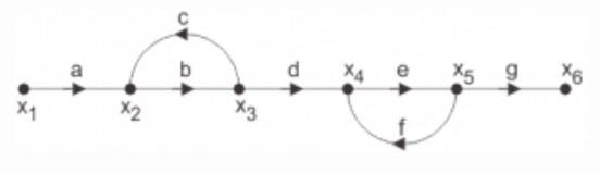
a) abd/1-(ac)
b) abdeg/1-(bc+ef)+bcef
c) abd/1-(bc+ef)+bcef
d) adcdef/1-(bc+ef)+bcef

Answer: b

Explanation: Using mason’s gain formula transfer function from signal flow graph can be calculated which relates the forward path gain to the various paths and loops.

4. Use mason’s gain formula to find the transfer function of the following signal flow graph:

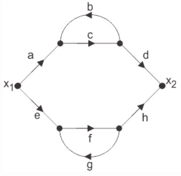
a) abcd+efg/1-cd-fg-cdfg
b) acdfg+bcefg/1-cd-fg-cdfg
c) abef+bcd/1-cd-fg-cdfg
d) adcdefg/1-cd-fg-cdfg

Answer: b

Explanation: Using mason’s gain formula transfer function from signal flow graph can be calculated which relates the forward path gain to the various paths and loops.

5. Loop which do not possess any common node are said to be ___________ loops.

a) Forward gain
b) Touching loops
c) Non touching loops
d) Feedback gain

Answer: c

Explanation: Loop is the part of the network in which the branch starts from the node and comes back to the same node and non touching loop must not have any node in common.

6. Signal flow graphs:

a) They apply to linear systems
b) The equation obtained may or may not be in the form of cause or effect
c) Arrows are not important in the graph
d) They cannot be converted back to block diagram

Answer: a

Explanation: Signal flow graphs are used to find the transfer function of control system by converting the block diagrams into signal flow graphs or directly but cannot be used for nonlinear systems.

7. Signal flow graphs are reliable to find transfer function than block diagram reduction technique.

a) True
b) False

Answer: a

Explanation: As one set technique and formula is used here but in block diagram technique various methods are involved which increases complexity.

8. The relationship between an input and output variable of a signal flow graph is given by the net gain between the input and output node is known as the overall______________

a) Overall gain of the system
b) Stability
c) Bandwidth
d) Speed

Answer: a

Explanation: The relationship between input and output variable of a signal flow graph is the overall gain of the system.

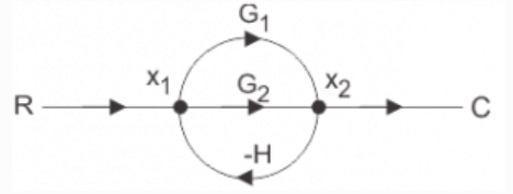
9. Use mason’s gain formula to calculate the transfer function of given figure:
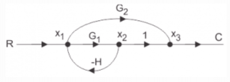
a) G1/1+G2H
b) G1+G2/1+G1H
c) G2/1+G1H
d) None of the mentioned

Answer: b

Explanation: Use mason’s gain formula to solve the signal flow graph and by using mason’s gain formula transfer function from signal flow graph can be calculated which relates the forward path gain to the various paths and loops.

10. Use mason’s gain formula to find the transfer function of the given figure:

a) G1+G2
b) G1+G1/1-G1H+G2H
c) G1+G2/1+G1H+G2H
d) G1-G2

Answer: c

Explanation: Using mason’s gain formula transfer function from signal flow graph can be calculated which relates the forward path gain to the various paths and loops.

Don't Miss Our Updates
Be the first to get exclusive content straight to your email.
We promise not to spam you. You can unsubscribe at any time.
Invalid email address
You've successfully subscribed !

Continue Reading

Stability of Nonlinear System
Level and Density Measurement Objective Questions
MCQ on Flow Measurement
Combination Electrode Questions & Answers
Encoder Multiple Choice Questions
Surface Spectroscopic Techniques
Share This Article
Facebook Whatsapp Whatsapp LinkedIn Copy Link
Share
Leave a Comment

Leave a Reply Cancel reply

Your email address will not be published. Required fields are marked *

Stay Connected

128.3kFollowersLike
69.1kFollowersFollow
210kSubscribersSubscribe
38kFollowersFollow

Categories

Explore More

Ion Analyzer Questions & Answers
Electron Spin Resonance
Mathematical Preliminaries
Liquid Scintillation Counters Questions & Answers
Atomic Absorption Spectroscopy Questions & Answers
Diagonalization
Routh-Hurwitz Stability Criterion
Flame Emission Photometers Questions & Answers

Keep Learning

State Variable Analysis and Design

Observer Systems

Control Systems Stability and Algebraic Criteria

Relative Stability Analysis

Radiochemical Questions and Answers

Fundamentals of Radiochemical Methods Questions

Spectrometers Questions and Answers

Total Reflection Spectrometer Questions & Answers

pH Analyzers Questions and Answers

Secondary Reference Electrodes Questions & Answers

Mathematical Models of Physical Systems

Differential Equations of Physical Systems & Dynamics of Robotic Mechanisms

Bipolar Junction Transistors Questions & Answers

Measurement and Instrumentation Objective Questions – Part 1

State Variable Analysis and Design

State Models for Linear Continuous Time Systems

Learn More

Units of Electrical Measurement

Units of Electrical Measurement

example-of-KCL

What is Kirchhoff’s Current Law

Digital Electronics Multiple Choice Questions

Multiplexers Objective Questions – Part 1

Absorption chiller

Capacity Control of Absorption Chillers

Field Instrument package

Package System Architecture – Control & Instrumentation

Thermovcouple Circuit

Thermocouple and its Principle

Hydrostatic interface level measurement Formula

Hydrostatic Interface Level Measurement

Voltmeter Calibration

Calibration Procedure of Voltmeter and Ammeter

Menu

  • About
  • Privacy Policy
  • Copyright

Quick Links

  • Learn PLC
  • Helping Hand
  • Part Time Job

YouTube Subscribe

Follow US
All rights reserved. Reproduction in whole or in part without written permission is prohibited.
Welcome Back!

Sign in to your account

Username or Email Address
Password

Lost your password?