Tank gauging is the generic name given to the measurement of liquids (product) in bulk storage tanks with the aim of quantifying how much product is in the tank, “gauging the contents of a tank”. Today, the oil & gas industry uses the static measurement of the tank contents to account for product stored and product moved into and out of the tank.
There are many instruments and systems available that can provide the combination of measurements that will allow an accurate quantity assessment and, hence, good inventory management. In Practice, we use both Radar and Servo Level Transmitters for Tank Gauges.
Servo Tank Gauges Principle
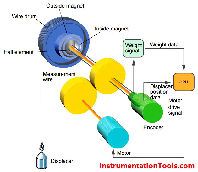
The Servo tank gauging system is based on the principle of displacement measurement. A small displacer is accurately positioned in the liquid medium using a servo motor. The displacer is suspended on a measuring wire that is wound onto a finely grooved drum housing within the instrument.

The drum is driven via coupling magnets, which are completely separated by the drum housing. Outer magnets are connected to the wire drum whilst the inner magnets are connected to the drive motor. As the magnets turn, the magnetic attraction causes the outer magnets to turn as well, resulting in turning the entire drum assembly. The weight of the displacer on the wire creates a torque on the outer magnets generating the change of magnetic flux. These changes generated between the drum assembly are detected by a unique electromagnetic transducer on the inner magnet. The drive motor is actuated to balance the voltage generated by the variations of magnetic flux to equal the reference voltage defined by the operating command.
When the displacer is lowered and touches the liquid, the weight of the displacer is reduced because of the buoyant force of the liquid. As a result, the torque in the magnetic coupling is changed and this change is measured usng Hall sensor, which are temperature compensated. The signal, an indication of the position of the displacer, is sent to the motor control circuit. As the liquid level rises and falls, the position of the displacer is adjusted by the drive motor. The rotation of the wire drum is precisely evaluated to determine the level value, which is accurate to an outstanding +/‐ 0.7 mm.
In this article, we are going to discuss about shutter door control using induction motor…
Electrical Drives control the motion of electric motors. Motion control is required in industrial and…
PLC ladder logic design to control 3 motors with toggle switch and explain the program…
VFD simulator download: Master the online tool from the Yaskawa V1000 & programming software for…
The conveyor sorting machine is widely used in the packing industries using the PLC program…
Learn the example of flip-flop PLC program for lamps application using the ladder logic to…
View Comments
ERS(ELECTRONIC REMOTE SENSOR ) TYPE LEVEL TRANSMITTER, IF ANY BODY HAVE PLEASE SEND ME DETAIL. NOW PROBLEM IS HART NOT CONNECT. DISPLAY SHOW DEVICE NOT FOUND. WE CHECK OUR SIDE IS CLEAR BUT THEN ALSO STILL PROBLEM STAND THEIR.
ANY BODY HAS SOLUTION LET ME INFORM ME.MINESH1925@GMAIL.COM