What is a Schottky Diode?
A Schottky diode, also known as a hot carrier diode, is a semiconductor diode which has a low forward voltage drop and a very fast switching action. There is a small voltage drop across the diode terminals when current flows through a diode. A normal diode will have a voltage drop between 0.6 to 1.7 volts, while a Schottky diode voltage drop is usually between 0.15 and 0.45 volts. This lower voltage drop provides better system efficiency and higher switching speed. In a Schottky diode, a semiconductor–metal junction is formed between a semiconductor and a metal, thus creating a Schottky barrier. The N-type semiconductor acts as the cathode and the metal side acts as the anode of the diode. This Schottky barrier results in both a low forward voltage drop and very fast switching.
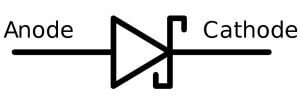
Fig : Schottky Diode Symbol
Schottky diodes are high-current diodes used primarily in high-frequency and fast-switching applications. They are also known as hot-carrier diodes. The term hot-carrier is derived from the higher energy level of electrons in the n region compared to those in the metal region. A Schottky diode symbol is shown in Above Figure. A Schottky diode is formed by joining a doped semiconductor region (usually n-type) with a metal such as gold, silver, or platinum. Rather than a pn junction, there is a metal-to-semiconductor junction, as shown in Below Figure. The forward voltage drop is typically around 0.3 V because there is no depletion region as in a pn junction diode.
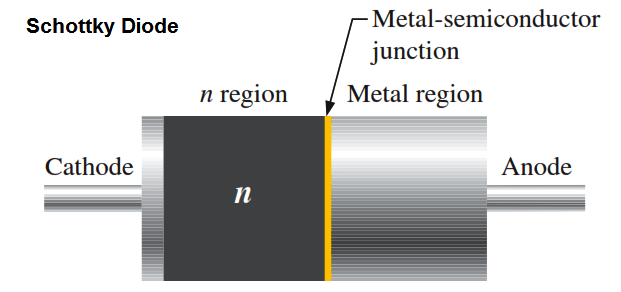
The Schottky diode operates only with majority carriers. There are no minority carriers and thus no reverse leakage current as in other types of diodes. The metal region is heavily occupied with conduction-band electrons, and the n-type semiconductor region is lightly doped. When forward-biased, the higher energy electrons in the n region are injected into the metal region where they give up their excess energy very rapidly. Since there are no minority carriers, as in a conventional rectifier diode, there is a very rapid response to a change in bias. The Schottky is a fast-switching diode, and most of its applications make use of this property. It can be used in high-frequency applications and in many digital circuits to decrease switching times.
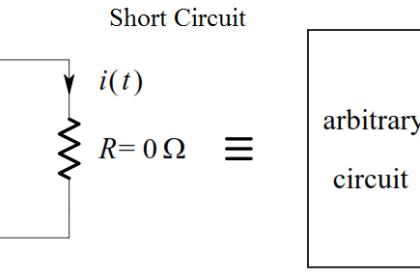
Equivalent circuit of schottky diode is given below
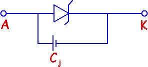
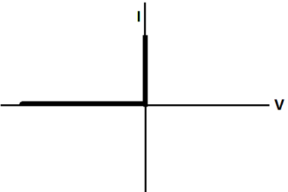
VI characteristics of Schottky barrier diode
From the VI characteristics it is obvious that the VI characteristics of Schottky barrier diode is similar to normal PN junction diode with the following exceptions
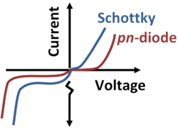
The forward voltage drop of Schottky barrier diode is low compared to normal PN junction diode. The forward voltage drop of Schottky barrier diode made of silicon exhibits a forward voltage drop of 0.3 volts to o.5 volts.
The forward voltage drop increases with the increasing doping concentration of n type semiconductor.
The VI characteristics of Schottky barrier diode is Steeper compared to VI characteristics of normal PN junction diode due to high concentration of current carriers.
Advantages
Schottky diodes are used in many applications where other types of diode will not perform as well. They offer a number of advantages:
- Low turn on voltage: The turn on voltage for the diode is between 0.2 and 0.3 volts for a silicon diode against 0.6 to 0.7 volts for a standard silicon diode. This makes it have very much the same turn on voltage as a germanium diode.
- Fast recovery time: The fast recovery time because of the small amount of stored charge means that it can be used for high speed switching applications.
- Low junction capacitance: In view of the very small active area, often as a result of using a wire point contact onto the silicon, the capacitance levels are very small.
The advantages of the Schottky diode, mean that its performance can far exceed that of other diodes in many areas.
Main Disadvantage
The main disadvantage of a schottky diode is that it has a relatively high reverse current. Because of its metal semiconductor junction, it is more suspectible to leaking current when voltage is connected in reverse. Also, schottky diodes tend to have low maximum reverse voltages. They tend to have a maximum value of 50V or less. Remember that the reverse voltage is the value in which the diode will break down and begin conducting a large amount of current when voltage is connected in reverse (from cathode to anode). This means schottky diodes cannot withstand much reverse voltage without breaking down and conducting large amounts of current. And even before reaching this maximum reverse value, it will still leak small amounts of current.
Depending on the application and use of the circuit, this may prove to be important or not.
Applications
The Schottky barrier diodes are widely used in the electronics industry finding many uses as diode rectifier. Its unique properties enable it to be used in a number of applications where other diodes would not be able to provide the same level of performance. In particular it is used in areas including:
- RF mixer and detector diode: The Schottky diode has come into its own for radio frequency applications because of its high switching speed and high frequency capability. In view of this Schottky barrier diodes are used in many high performance diode ring mixers. In addition to this their low turn on voltage and high frequency capability and low capacitance make them ideal as RF detectors.
- Power rectifier: Schottky barrier diodes are also used in high power applications, as rectifiers. Their high current density and low forward voltage drop mean that less power is wasted than if ordinary PN junction diodes were used. This increase in efficiency means that less heat has to be dissipated, and smaller heat sinks may be able to be incorporated in the design.
- Power OR circuits: Schottky diodes can be used in applications where a load is driven by two separate power supplies. One example may be a mains power supply and a battery supply. In these instances it is necessary that the power from one supply does not enter the other. This can be achieved using diodes. However it is important that any voltage drop across the diodes is minimised to ensure maximum efficiency. As in many other applications, this diode is ideal for this in view of its low forward voltage drop.Schottky diodes tend to have a high reverse leakage current. This can lead to problems with any sensing circuits that may be in use. Leakage paths into high impedance circuits can give rise to false readings. This must therefore be accommodated in the circuit design.