Inst ToolsInst ToolsInst Tools
  • Courses
  • Automation
    • PLC
    • Control System
    • Safety System
    • Communication
    • Fire & Gas System
  • Instrumentation
    • Design
    • Pressure
    • Temperature
    • Flow
    • Level
    • Vibration
    • Analyzer
    • Control Valve
    • Switch
    • Calibration
    • Erection & Commissioning
  • Interview
    • Instrumentation
    • Electrical
    • Electronics
    • Practical
  • Q&A
    • Instrumentation
    • Control System
    • Electrical
    • Electronics
    • Analog Electronics
    • Digital Electronics
    • Power Electronics
    • Microprocessor
  • Request
Search
  • Books
  • Software
  • Projects
  • Process
  • Tools
  • Basics
  • Formula
  • Power Plant
  • Root Cause Analysis
  • Electrical Basics
  • Animation
  • Standards
  • 4-20 mA Course
  • Siemens PLC Course
Reading: Reactive Power Sources and Sinks in Power System
Share
Notification Show More
Font ResizerAa
Inst ToolsInst Tools
Font ResizerAa
  • Courses
  • Design
  • PLC
  • Interview
  • Control System
Search
  • Courses
  • Automation
    • PLC
    • Control System
    • Safety System
    • Communication
    • Fire & Gas System
  • Instrumentation
    • Design
    • Pressure
    • Temperature
    • Flow
    • Level
    • Vibration
    • Analyzer
    • Control Valve
    • Switch
    • Calibration
    • Erection & Commissioning
  • Interview
    • Instrumentation
    • Electrical
    • Electronics
    • Practical
  • Q&A
    • Instrumentation
    • Control System
    • Electrical
    • Electronics
    • Analog Electronics
    • Digital Electronics
    • Power Electronics
    • Microprocessor
  • Request
Follow US
All rights reserved. Reproduction in whole or in part without written permission is prohibited.
Inst Tools > Blog > Power Systems > Reactive Power Sources and Sinks in Power System

Reactive Power Sources and Sinks in Power System

Last updated: September 20, 2016 2:24 pm
Editorial Staff
Power Systems
No Comments
Share
2 Min Read
SHARE

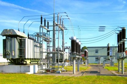
Dynamic Reactive Power Sources:

It includes reactive power compensators which have the ability to respond within duration of cycles and try to balance the reactive power requirement in the system. They are considered as transmission service equipment or devices. These devices respond to change in the reactive power requirement in the system quickly and provides or injects the sufficient reactive power into the system.Some of the dynamic sources which acts as sources to the reactive power are:

  • Synchronous generators
  • Synchronous condensers
  • Solid state devices such as FACT devices (STATCOM, SVC)

Synchronous generators controls the reactive power to be delivered with the help of Automatic Voltage Regulator (AVR). The maximum capacity of synchronous machines (both synchronous generators and synchronous condensers) to deliver the reactive power (MVAR) is limited with in the operation region of P-Q diagram and system stability limits.

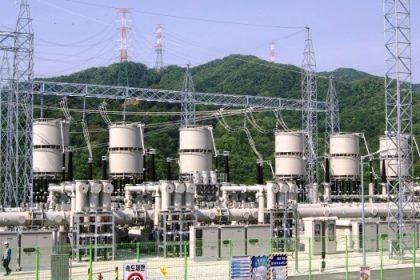
Static Reactive Power Sources: 

Static sources generally static in nature to the change in the reactive power requirement in the system. They deliver constant reactive power to the system irrespective of the system requirement. These devices are inexpensive but communication, control and associated switching and maintenance requires huge amount.Some of the static sources for the reactive power in the power system are:
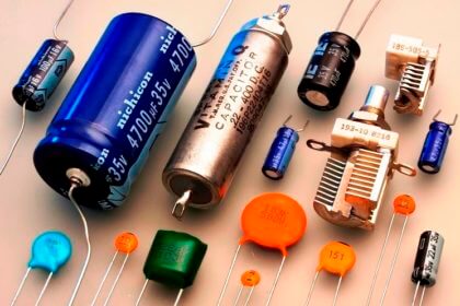
  • Shunt capacitors
  • Filter banks
  • Underground cables
  • Transmission lines when lightly loaded
  • Fuel cells
  • PV systems

Reactive Power Sinks: 

Reactive power generated by synchronous generators and other devices in the power system is absorbed or consumed by the loads. Therefore it is advisable to place the reactive power compensation devices at the load centers so that losses associated with transmission of reactive power to load centers is reduced. Some of the sinks for reactive power in the power system are listed below:

  • Induction motors(pumps, fans)
  • induction loads (Arc furnace, heaters)
  • Induction generators
  • Synchronous machines (under excited)
  • Transmission lines heavily loaded
  • Transformers
  • Shunt reactors
Don't Miss Our Updates
Be the first to get exclusive content straight to your email.
We promise not to spam you. You can unsubscribe at any time.
Invalid email address
You've successfully subscribed !

Continue Reading

Voltage Variations Effects on Power Plant Equipment
Why Reactive Power is Generated at Load
Generating Station Grounding Principles
Advantages and Disadvantages of Per Unit System
Underground Cable Fault Identification Methods
Ungrounded or Isolated Neutral System Disadvantages
Share This Article
Facebook Whatsapp Whatsapp LinkedIn Copy Link
Share
Leave a Comment

Leave a Reply Cancel reply

Your email address will not be published. Required fields are marked *

Stay Connected

128.3kFollowersLike
69.1kFollowersFollow
210kSubscribersSubscribe
38kFollowersFollow

Categories

Explore More

Auto Recloser Circuit Breaker in Power System
Electrical Power System Protection Quiz
Harmonics Disadvantages in Power System
Shunt Capacitor Advantages in Power System
Why Symmetrical Components Used for Unbalanced faults in Power System
Factors affect Voltage Level Selection in Service System
Power System Protection Multiple Choice Questions
Harmonics effect on Induction Motor

Keep Learning

Silicon Carbide Lightning Arresters Working Principle

current-limiting-reactors-and-short-circuit-currents

Current Limiting Reactors and Short Circuit Currents

Transformer Tap changer

Ferroresonance in Power Transformers

Advantages & Disadvantages of AC power and DC power

Advantages & Disadvantages of AC power and DC power

neutral-grounding-practice-in-power-system

Neutral Grounding Practice in Power System

Rotor Angle Stability of Synchronous Generators in Power System

Rotor Angle Stability of Synchronous Generators in Power System

harmonics-effect-on-transformer

Harmonics effect on Transformer

Corona-Ring-on-Surge-Arresters

Corona Ring on Surge Arresters and other EHV equipment

Learn More

Understanding Braking Theory in VFD

Understanding Braking Theory in VFD

Turbine to Gearbox Alignment Drifts Caused Pump Transfers Problems

RCA Related to Trip Throttle Valve (TTV)

How to use PLC With SQL Database

How to use PLC with SQL Database? – Basics & Tutorials

Conductivity Meter for Medium Concentration

Measurement of Impurities in Water and Steam – Power Plant

Look Listen Feel of Instruments

Look Listen Feel of Instruments – Instrumentation Engineer Maintenance

Pull Cord Switch Principle

Pull Cord Switch Working Principle

Measurement of Impedance Objective Questions

Measurement of Impedance Objective Questions

Pressure based Flowmeters

Pressure based Flow Meters

Menu

  • About
  • Privacy Policy
  • Copyright

Quick Links

  • Learn PLC
  • Helping Hand
  • Part Time Job

YouTube Subscribe

Follow US
All rights reserved. Reproduction in whole or in part without written permission is prohibited.
Welcome Back!

Sign in to your account

Username or Email Address
Password

Lost your password?