Inst ToolsInst ToolsInst Tools
  • Courses
  • Automation
    • PLC
    • Control System
    • Safety System
    • Communication
    • Fire & Gas System
  • Instrumentation
    • Design
    • Pressure
    • Temperature
    • Flow
    • Level
    • Vibration
    • Analyzer
    • Control Valve
    • Switch
    • Calibration
    • Erection & Commissioning
  • Interview
    • Instrumentation
    • Electrical
    • Electronics
    • Practical
  • Q&A
    • Instrumentation
    • Control System
    • Electrical
    • Electronics
    • Analog Electronics
    • Digital Electronics
    • Power Electronics
    • Microprocessor
  • Request
Search
  • Books
  • Software
  • Projects
  • Process
  • Tools
  • Basics
  • Formula
  • Power Plant
  • Root Cause Analysis
  • Electrical Basics
  • Animation
  • Standards
  • 4-20 mA Course
  • Siemens PLC Course
Reading: Pressure Unit Conversion Practical Example
Share
Font ResizerAa
Inst ToolsInst Tools
Font ResizerAa
  • Courses
  • Design
  • PLC
  • Interview
  • Control System
Search
  • Courses
  • Automation
    • PLC
    • Control System
    • Safety System
    • Communication
    • Fire & Gas System
  • Instrumentation
    • Design
    • Pressure
    • Temperature
    • Flow
    • Level
    • Vibration
    • Analyzer
    • Control Valve
    • Switch
    • Calibration
    • Erection & Commissioning
  • Interview
    • Instrumentation
    • Electrical
    • Electronics
    • Practical
  • Q&A
    • Instrumentation
    • Control System
    • Electrical
    • Electronics
    • Analog Electronics
    • Digital Electronics
    • Power Electronics
    • Microprocessor
  • Request
Follow US
All rights reserved. Reproduction in whole or in part without written permission is prohibited.
Inst Tools > Blog > Pressure Measurement > Pressure Unit Conversion Practical Example

Pressure Unit Conversion Practical Example

Last updated: May 21, 2020 5:03 pm
Editorial Staff
Pressure Measurement
No Comments
Share
3 Min Read
SHARE

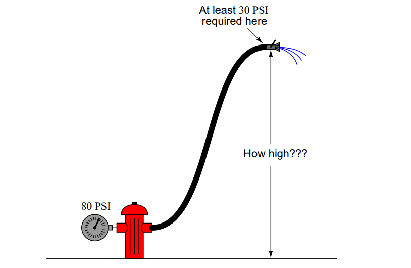
Water pressure available at a fire hydrant is 80 PSI. If a fire hose is connected to the hydrant and the hydrant valve opened, how high can the end of the hose be raised and still have water flow out the end?

Pressure Unit Conversion Example

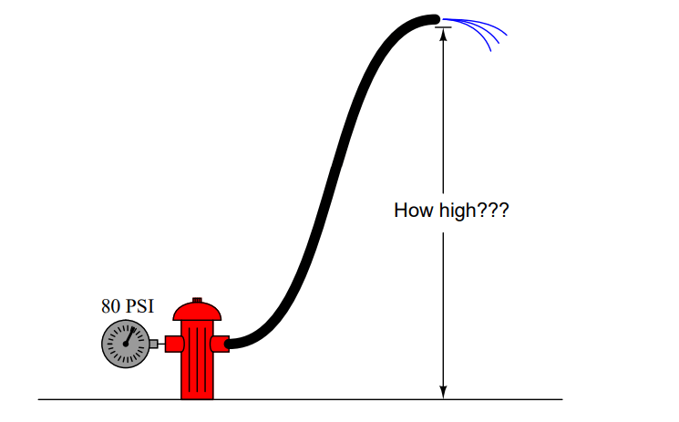
Now, suppose that a spray nozzle attached to the end of the hose requires at least 30 PSI of pressure at the coupling in order to create a proper spray of water. How high can the hose be raised then, and still have enough water pressure at the nozzle to allow for the fighting of a fire?

Pressure Unit Conversion Practical Example

Answer:

With no nozzle on the end of the hose, the end may be raised a maximum of 184.54 feet. With a nozzle in place, the hose end may be raised only 115.33 feet. Essentially, this is just another pressure unit conversion problem: in this case, PSI-to-feet of water column. 80 PSI is equivalent to 184.54 feet, so that is how high 80 PSI can force a column of water.

With a nozzle attached to the end of the hose, though, we are only allowed to “drop” 50 feet of hydrostatic pressure, in order to leave 30 PSI remaining at the nozzle coupling for proper operation. 50 PSI is equivalent to 115.33 feet, so this is how high we may raise the hose end with a nozzle on it.

It must be understood that the first calculation is not a very practical one. 80 PSI of pressure at the hydrant will just push water 184.54 feet high. If the hose were 190 feet and poised vertically, there would be a column of water inside 184.54 feet tall, with no water at all coming out the end. If the hose end were brought exactly to a height of 184.54 feet, water would be right at the lip of the hose, not even trickling out. Obviously, some pressure is needed at the hose end in order to push water out onto a fire, so the practical, no-hose height for 80 PSI will be somewhat lower than 184.54 feet.

The hose-with-nozzle scenario is more realistic, because an actual figure for minimum hose-end pressure is given for us to incorporate into our calculations.

Read Next:

  • Instrument Percent of Span Error
  • Analog and Digital Signals
  • Pneumatic Control Loop
  • Float & Dial Level Gauge
  • Pressure Transmitter Circuit

Credits: Tony R. Kuphaldt

Don't Miss Our Updates
Be the first to get exclusive content straight to your email.
We promise not to spam you. You can unsubscribe at any time.
Invalid email address
You've successfully subscribed !

Continue Reading

Difference between Axial and Radial Diaphragm Seal Connection?
Information on the Pressure Gauge Dial
What is Capillary Tubing? – Advantages and Disadvantages
Diaphragm Seal Transmitters Errors
Basics of Pressure Measurement
15 HART Communicator Questions
Share This Article
Facebook Whatsapp Whatsapp LinkedIn Copy Link
Share
Leave a Comment

Leave a Reply Cancel reply

Your email address will not be published. Required fields are marked *

Stay Connected

128.3kFollowersLike
69.1kFollowersFollow
210kSubscribersSubscribe
38kFollowersFollow

Categories

Explore More

Pressure Gauge Water Traps and Pigtail Siphons
Pressure Gauge Calibration Procedure
Gage and Absolute Pressure Transmitters Principle
U-tube Manometer with equal & unequal limb types
Pressure Transmitter Circuit
Differential Pressure Transmitter Calibration Procedure
Why are Impulse Lines often Installed in a Sloping Manner?
Pressure Transmitters Heat-traced impulse lines

Keep Learning

Pressure Transmitter Troubleshooting Tips

Pressure Transmitter Troubleshooting Tips

Pressure Transmitter Calibration Setup

Pressure Transmitter Preventive Maintenance

Difference between Absolute, Gauge and Differential Pressure Transmitters

Difference between Absolute, Gauge and Differential Pressure Transmitters

Inclined-limb Manometer Formula - 2

Inclined-limb Manometer Principle

Advantages of Pneumatic Systems in the Automotive Industry

Advantages of Pneumatic Systems in the Automotive Industry

Capacitance Pressure Sensor Works

How Capacitive Pressure Sensor Works ?

pressure transmitter calibration setup

Questions on Pressure Transmitter Calibration Setup

Barometer Principle

What is a Barometer?

Learn More

PLC Sequential Operation Example Program

PLC Sequential Operation Example Program

RTD Graph

Calculate Temperature Coefficient of RTD

Calibrate Eddy Current Conductivity Instrument

How to Calibrate the Eddy Current Conductivity Meter?

Power Electronics Objective Questions

1 Phase Voltage Source Inverter Quiz

Electrical Component Symbols

Electrical Diagrams and Schematics

Three-Phase Wye Wiring System

4-Wire, Three-Phase Wye Wiring System

Refrigeration Compressor Turbine Not-tripping when needed Trip

Refrigeration Compressor Turbine Not-tripping when needed Trip

Differential Pressure Flow Meters

Short Notes on Differential Pressure Flow Meters

Menu

  • About
  • Privacy Policy
  • Copyright

Quick Links

  • Learn PLC
  • Helping Hand
  • Part Time Job

YouTube Subscribe

Follow US
All rights reserved. Reproduction in whole or in part without written permission is prohibited.
Welcome Back!

Sign in to your account

Username or Email Address
Password

Lost your password?