Inst ToolsInst ToolsInst Tools
  • Courses
  • Automation
    • PLC
    • Control System
    • Safety System
    • Communication
    • Fire & Gas System
  • Instrumentation
    • Design
    • Pressure
    • Temperature
    • Flow
    • Level
    • Vibration
    • Analyzer
    • Control Valve
    • Switch
    • Calibration
    • Erection & Commissioning
  • Interview
    • Instrumentation
    • Electrical
    • Electronics
    • Practical
  • Q&A
    • Instrumentation
    • Control System
    • Electrical
    • Electronics
    • Analog Electronics
    • Digital Electronics
    • Power Electronics
    • Microprocessor
  • Request
Search
  • Books
  • Software
  • Projects
  • Process
  • Tools
  • Basics
  • Formula
  • Power Plant
  • Root Cause Analysis
  • Electrical Basics
  • Animation
  • Standards
  • 4-20 mA Course
  • Siemens PLC Course
Reading: Pressure Transmitter Troubleshooting Tips
Share
Font ResizerAa
Inst ToolsInst Tools
Font ResizerAa
  • Courses
  • Design
  • PLC
  • Interview
  • Control System
Search
  • Courses
  • Automation
    • PLC
    • Control System
    • Safety System
    • Communication
    • Fire & Gas System
  • Instrumentation
    • Design
    • Pressure
    • Temperature
    • Flow
    • Level
    • Vibration
    • Analyzer
    • Control Valve
    • Switch
    • Calibration
    • Erection & Commissioning
  • Interview
    • Instrumentation
    • Electrical
    • Electronics
    • Practical
  • Q&A
    • Instrumentation
    • Control System
    • Electrical
    • Electronics
    • Analog Electronics
    • Digital Electronics
    • Power Electronics
    • Microprocessor
  • Request
Follow US
All rights reserved. Reproduction in whole or in part without written permission is prohibited.
Inst Tools > Blog > Pressure Measurement > Pressure Transmitter Troubleshooting Tips

Pressure Transmitter Troubleshooting Tips

Last updated: December 7, 2018 9:13 am
Editorial Staff
Pressure Measurement
1 Comment
Share
2 Min Read
SHARE

The below list provides the list of general pressure transmitter problems and their possible corrective actions.

Transmitter milliamp reading is zero

  • Verify power is applied to signal terminals
  • Check power wires for reversed polarity
  • Verify terminal voltage is 10.5 to 42.4 Vdc
  • Check for open diode across test terminal

Transmitter Not Communicating with Field Communicator

  • Verify the output is between 4 and 20 mA or saturation levels
  • Verify terminal voltage is 10.5 to 42.4 Vdc
  • Verify clean DC Power to transmitter (Max AC noise 0.2 volts peak to peak)
  • Check loop resistance, 250 ohms minimum (Power supply voltage -transmitter voltage/loop current)
  • Have Field Communicator poll for all addresses

Transmitter milliamp reading is low or high

  • Verify applied pressure
  • Verify 4 and 20 mA range points
  • Verify output is not in alarm condition (Alarm option available in some transmitters)
  • Verify if 4 – 20 mA output trim is required

Transmitter will not respond to changes in applied pressure

  • Check test equipment
  • Check impulse piping or manifold for blockage
  • Verify the transmitter is not in multidrop mode
  • Verify applied pressure is between the 4 and 20 mA set points
  • Verify output is not in alarm condition
  • Verify transmitter is not in Loop Test mode

Digital Pressure Variable reading is low or high

  • Check test equipment (verify accuracy)
  • Check impulse piping for blockage or low fill in wet leg
  • Verify transmitter is calibrated properly
  • Verify pressure calculations for application

Digital Pressure Variable reading is erratic 

  • Check application for faulty equipment in pressure line
  • Verify transmitter is not reacting directly to equipment turning on/off
  • Verify damping is set properly for application

Milliamp reading is erratic 

  • Verify power source to transmitter has adequate voltage and current
  • Check for external electrical interference
  • Verify transmitter is properly grounded
  • Verify shield for twisted pair is only grounded at one end

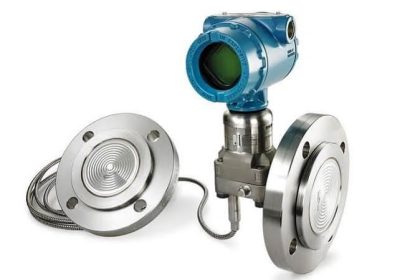
Reference : Rosemount 

Don't Miss Our Updates
Be the first to get exclusive content straight to your email.
We promise not to spam you. You can unsubscribe at any time.
Invalid email address
You've successfully subscribed !

Continue Reading

Pressure Measurement Objective Questions
How much Pressure applied to U-tube Water Manometer?
Difference between Axial and Radial Diaphragm Seal Connection?
Installation and Calibration of Pressure Transmitter
Pressure Transmitter Preventive Maintenance
Magnehelic Gauge Calibration
Share This Article
Facebook Whatsapp Whatsapp LinkedIn Copy Link
Share
1 Comment
  • Abdel-rahman says:
    March 20, 2017 at 3:22 pm

    very good tips.

    Reply

Leave a Reply Cancel reply

Your email address will not be published. Required fields are marked *

Stay Connected

128.3kFollowersLike
69.1kFollowersFollow
210kSubscribersSubscribe
38kFollowersFollow

Categories

Explore More

How Capacitive Pressure Sensor Works ?
Pressure Gauges Zero Adjustment
Differential Pressure Switch Calibration Procedure
Types of Pressure Measuring Scales
Strain Gauge Working Principle
McLeod Gauge Working Principle
What are Impulse Lines? – Impulse Line Problems & Solutions
Resistance Type Pressure Transducers Principle

Keep Learning

Absolute Pressure Gauges Principle

Absolute Pressure Gauges Principle

Identify the Pressure Gauge Error

Identify the Pressure Gauge Error

Impulse Line Purging and Close Coupling

Impulse Line Purging and Close Coupling of Instruments

Asymmetric capillary for Level Measurement

Effects of Symmetric and Asymmetric Capillary Tube Pressure Measurement

What are Pressure Sensing Lines

What are Pressure Sensing Lines? – Causes of Errors in Measurement

Principle of Elastic diaphragm gauges

Elastic Diaphragm Gauge Principle

pressure-switch-calibration-procedure

Pressure Switch Calibration Procedure

Pressure Gauge Accessories

Pressure Gauge Accessories

Learn More

Hot Well Level Control System in Condensing Turbine

Hot Well Level Control System in Condensing Turbine

Run 4 Motors Sequentially from Same Push button PLC Program

Run 4 Motors Sequentially from Same Push button PLC Program

triac

Turning Off SCR – Commutation

Electric Circuits Objective Questions

Electric Circuits Objective Questions – Set 11

Siemens CPU MP Port

Siemens S7-300 CPU Suffix Explanation

Pressure Transmitter Impulse Lines Heat Trace

Pressure Transmitters Heat-traced impulse lines

Zigzag Transformers Theory

Zigzag Transformers Theory

Pneumatic Counter for Counting the Strokes of a Cylinder

Pneumatic Counter for Counting the Strokes of a Cylinder

Menu

  • About
  • Privacy Policy
  • Copyright

Quick Links

  • Learn PLC
  • Helping Hand
  • Part Time Job

YouTube Subscribe

Follow US
All rights reserved. Reproduction in whole or in part without written permission is prohibited.
Welcome Back!

Sign in to your account

Username or Email Address
Password

Lost your password?