In this article, you will learn about pressure sensing lines, dynamic testing of impulse lines, and causes of errors in pressure measurement.
Contents
What do You Mean by Dynamic Pressure?
- Dynamic pressure is defined as the pressure of a fluid such as gas or liquid is momentum transfer from molecules to the object on which pressure acts.
- The magnitude of pressure depends on the number of molecules and the momentum of the molecules that impact the surface on which pressure is measured.
- Mathematically, Pressure P is generally represented as net force F, perpendicular to a surface of area A. P= F/A
- When pressure remains constant for a significant time period during the complete measurement it is referred to as Static Pressure.
- On the other hand, when pressure varies significantly over a specific time period during the complete measurement it is referred to as Dynamic Pressure.
- But in this condition, what is desired is not a single time-invariant pressure value, but a kind of time-dependent pressure function.
- The definition of static pressure and dynamic pressure may not be used but these are common in fluid flow,
- Note that, Static pressure is defined as the pressure at the point of zero speed of fluid flow.
- Dynamic pressure is defined as the collision pressure due to the motion of the fluid particle.
- Dynamic pressure is used to determine the airspeed of the aircraft.
- The sum of Static Pressure and Dynamic Pressure gives the Actual Pressure.
Actual Pressure = Static Pressure + Dynamic Pressure
Measurement of Dynamic Pressure
- Measurement of dynamic pressure in process industries and power plants is done in various fields such as combustion analysis in combustion control, automotive industry, turbo machinery, and aerodynamics.
- The encountered amplitudes range from a few Pascal to several Giga Pascal. And frequencies range below one Hz to about one MHz.
- The dynamic pressure is about 50% of the air density times the airspeed squared.
- The project engineer should not be satisfied with a minimal collection of data for .measurement.
- Data used for measurement must be calculated and reported with an adjoining statement of measurement traceability and uncertainty.
- The uncertainty statement describes the quality of data estimated by operators using stated methods and equipment.
- Without having reliable data and information about data quality for measurement is a risk.
- In the case of static and dynamic pressure measurement, traceability and uncertainty analyses account for the big difference
- Due to this difference, the pressure transducers are only calibrated for static pressures.
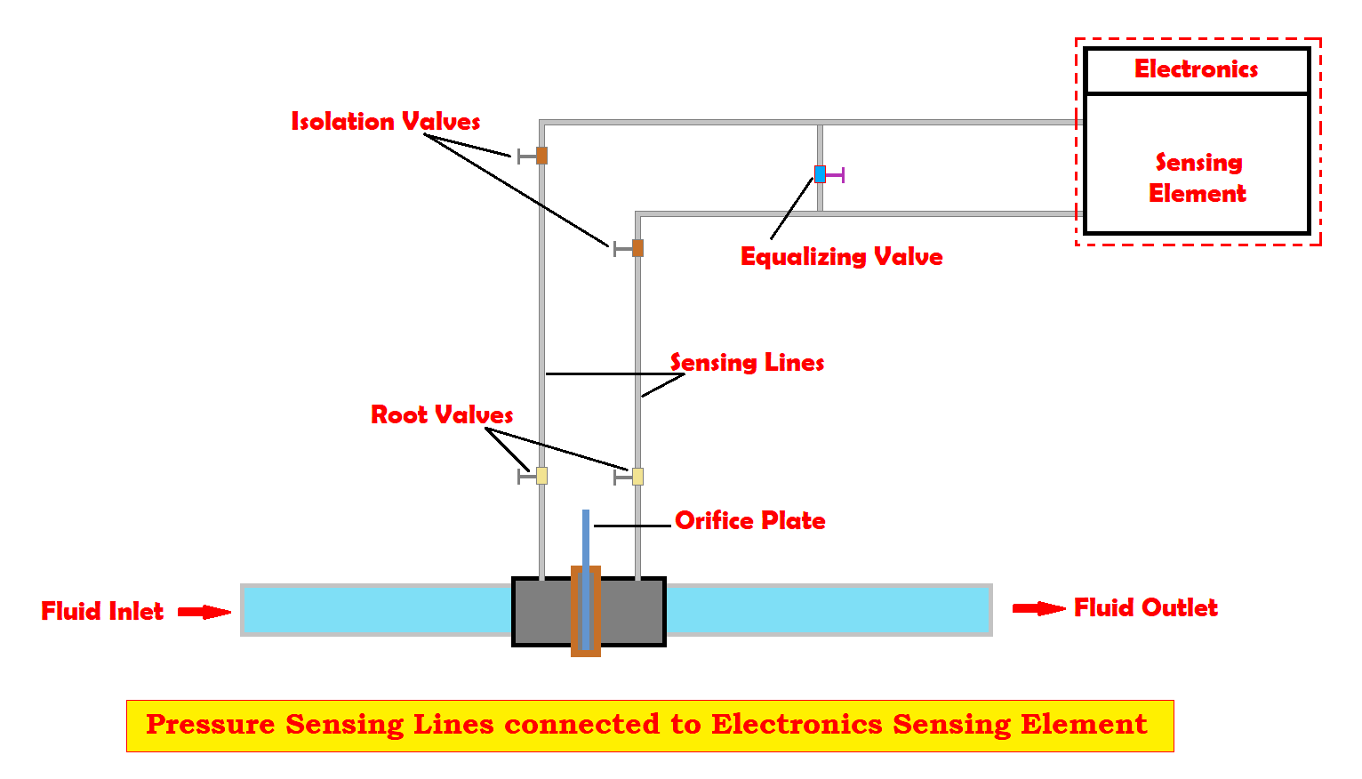
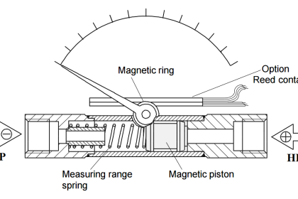
What are Pressure Sensing Lines?
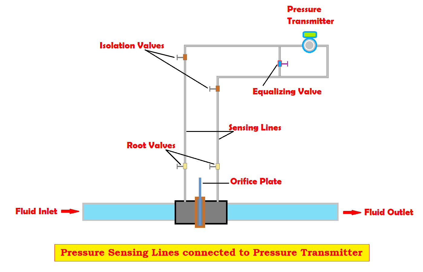
- Sensing lines are also known as impulse lines.
- This sensing line enables the position of pressure transmitters that are located away from the process station.
- An impulse line reduces the effect of temperature on transmitters’ performance and operation.
- The high ambient (atmospheric) temperature will influence the mechanical components of the transmitter and reduces the life span of its solid-state electronics.
- Positioning pressure transmitters quite away from the process station will minimize the bad effects of vibration and simplifies for maintenance or replacement of pressure transmitter.
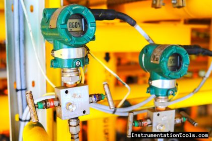
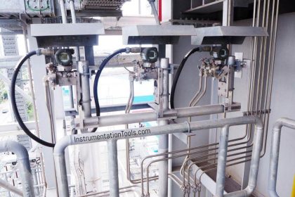
- Figure 1 and Figure 2 represent two different impulse lines.
- From these figures, the sensing lines or impulse lines connect the process to the pressure transmitter.
- Based on the application type, there may be one or two sensing lines for each pressure transmitter.
- Every industrial process uses both liquid-filled and gas-filled sensing lines.
- Depending upon the application and design
- A liquid-filled sensing line generally contains process fluids such as oil or any liquid.
- A gas-filled sensing line contains steam, air, nitrogen, or other gases.
- In some cases, there is a passage in impulse line to another medium such as oil or water.
- For the transition from one medium to another medium, a diaphragm, bellows, or condensate pot is used in impulse lines.
- Sensing lines or impulse lines are generally small diameter pipes with 1.5 cm to 2.0 cm made of stainless steel, carbon steel, or carbon tubing.
- The thickness of carbon tubing is about 2mm.
- Tubing is installed in a single piece and reduces the chance of leakage.
- The length of sensing lines varies based on application, generally, the length may be about 300 meters, but on average the length is about 40 meters to 50 meters.
- Installation of sensing lines is designed to allow thermal expansion and vibration without deformation and to verify drainage by gravity.
- Self-venting is adopted by sloping impulse lines to the process in a downward direction to vent out any gas or air present in liquid lines.
- The slope of a sensing line is about 10 cm per meter.
- If there no slope provides in sensing lines
- A high-point vent is required for liquid.
- A low-point vent is required for gas.
What are the Causes of Errors in Pressure Measurement?
Voids, blockages, leaks, or freezing in sensing lines causes errors in pressure measurements. And it also affects the dynamic response of the pressure-sensing system.
Voids
- Air or gas snared in liquid sensing lines causes false pressure readings and sluggish response.
- For example: in DP measurements, an air pocket snared on the LP causes pressure indication to be higher than usual.
Blockages
- Clogging in sensing lines occur when chemicals are used in water treatment and mud particles solidifies when other impurities get deposited.
- These also occur due to blockage caused by improper alignment of isolation and equalizing valves due to sensing lines getting crimped.
Leakage
- Pressure sensing lines issue many possibilities for leakage to arise.
- A sensing line consists of equalizing valve, one or more root valves, and isolation valves.
- Some other connections under high working pressures may rise to leakage problems.
- Remarkable fluid in a sensing line causes a false pressure indication.
Freezing
- Freezing locks normal operating pressure into the system.
- During cold weather or in winter freezing occurs in sensing lines if the heat tracing used to prevent fluid freezing is aged or damaged.
Pressure Sensing-Line Problems Solving
- Periodic blowdown, backfill, or draining of impulse lines are the best remedies to eliminate Voids and blockages in impulse lines.
- Testing and monitoring the presence of voids or blockages in impulse lines is carried out by noise analysis technique.
- The main advantage of the noise analysis technique is that the results include the effects of sensing lines.
- The response time result will inherently account for the length, and diameter of sensing lines and blockages, voids, leaks, or freezing present in the sensing lines.
If you liked this article, then please subscribe to our YouTube Channel for Electrical, Electronics, Instrumentation, PLC, and SCADA video tutorials.
You can also follow us on Facebook and Twitter to receive daily updates.
Read Next:


Firstly, any orifice plate used for measuring LIQUID flow HAS to be mounted ABOVE the level of the transmitter to allow for the liquid to fill both HP: and LP legs.
For any gas flow, this geometry is reversed, with the transmitted mounted ABOVE the dp cell.
Secondly, the Isolating valves shown on the diagram are too far from their respective objectives: The Orifice plate has these mounted directly on the pipeline, either at D and D/2 Upstream and downstream respectively, or on the orifice plate carrier ring itself in the case of flange taps. The Isolation valves at the dp cell are normally incorporated into a 3 valve SS manifold, bolted directly on to the transmitter.