Pressure is defined as a force per unit area – and the most accurate way to measure low air pressure is to balance a column of liquid of known weight against it and measure the height of the liquid column so balanced. The units of measure commonly used are inches of mercury (in. Hg), using mercury as the fluid and inches of water (in. w.c.), using water or oil as the fluid.
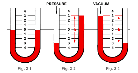
Fig. 2-1. In its simplest form the manometer is a U-tube about half filled with liquid. With both ends of the tube open, the liquid is at the same height in each leg.
Fig. 2-2. When positive pressure is applied to one leg, the liquid is forced down in that leg and up in the other. The difference in height, “h,” which is the sum of the readings above and below zero, indicates the pressure.
Fig. 2-3. When a vacuum is applied to one leg, the liquid rises in that leg and falls in the other. The difference in height, “h,” which is the sum of the readings above and below zero, indicates the amount of vacuum.
Instruments employing this principle are called manometers. The simplest form is the basic and well-known U-tube manometer. (Fig. 2-1). This device indicates the difference between two pressures (differential pressure), or between a single pressure and atmosphere (gage pressure), when one side is open to atmosphere. If a U-tube is filled to the half way point with water and air pressure is exerted on one of the columns, the fluid will be displaced. Thus one leg of water column will rise and the other falls. The difference in height “h” which is the sum of the readings above and below the half way point, indicates the pressure in inches of water column.
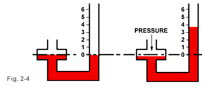
Fig. 2-4. At left, equal pressure is imposed on the fluid in the well and in the indicating tube. Reading is zero. At the right, a positive pressure has been imposed on the liquid in the well causing the level to go down very slightly. Liquid level in indicating tube has risen substantially. Reading is taken directly from scale at liquid level in indicating tube. The scale has been compensated for the drop in level in the well.
The U-tube manometer is a primary standard because the difference in height between the two columns is always a true indication of the pressure regardless of variations in the internal diameter of the tubing. This provides a real convenience to the person who might otherwise have to board an airplane carrying a 60″ long rigid glass U-tube manometer.
Variations in Manometer Design
To overcome the U-tube requirement of readings at two different places, the well-type manometer was developed. See Fig. 2-4. The reservoir (well) may be made large enough so that the change of level in the reservoir is negligible, or the scale may be compensated for the change in reservoir liquid level. For purposes of a more practical instrument the well-type manometer uses a precision bored well that requires approximately a 10% scale correction for well drop effect, thus avoiding an overly large and bulky reservoir.
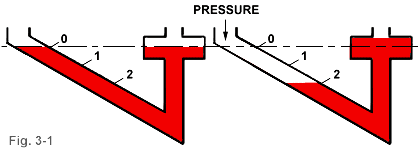
To improve and expand readability, certain U-type and well-type manometers are available with a .826 sp. gr. red oil indicating fluid, and scales compensated to read pressure directly in inches of water. To further increase readability and sensitivity the well-type manometer indicating tube is inclined, as in Fig. 3-1, to cause a greater linear movement along the tube for a given pressure difference. The inclined manometer is frequently called a Draft Gage because it is widely used for determining the over-fired draft in boiler uptakes and flues.
For an inclined manometer to be a primary device, the inclined tube must be straight and uniform. Precision machined solid plastic construction has been applied to a basic line of rugged manometers, inclined and inclined-vertical, which are industry accepted as primary instruments.
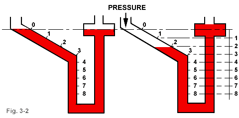
Fig. 3-2. At left, with equal pressure on liquid in well and indicating tube, reading is zero. When positive pressure is imposed on liquid in indicating tube, liquid level is depressed in tube and rises slightly in well. Reading is direct since scale is compensated for change of level in well.
The combination of an inclined and a vertical manometer is very useful in air movement determination. See Fig. 3-2. For air velocity measurement, an inclined scale, generally up to 1″ w.c. is used (1″ w.c. velocity pressure = 4000 fpm). In the inclined-vertical instrument, this scale is combined with a vertical section allowing readings of high pressures, usually 1″ w.c. to 5 to 10″ w.c., to be taken. The vertical section is used primarily for determining static pressure above the range of the inclined section. Many special purpose types of manometers exist.
Factors Affecting Manometer Performance & Usage
While the basic manometer principle of hydrostatic balance is inherently 100% accurate there are factors that can affect the actual pressure measurement obtained. Careful design and construction plus careful usage can eliminate or greatly reduce the effect of these factors.
Characteristics of Indicating Fluid
No manometer can be read more accurately than the accuracy with which the specific gravity of the fluid is known. The fluid must also have good “wetting” characteristics and be capable of forming a consistent, well shaped meniscus in the indicating tube to facilitate accurate, repeatable readings.
The fluid used also affects the operating range of the manometer. Mercury being 13.6 times the weight of water will move 1/13.6th the distance water will move in response to a given pressure. Oil being lighter than water will move about 1.2 times farther than water in response to a given pressure. This, obviously, expands the scale for easier, more precise reading.
U-tube and well-type manometers are furnished with inch scales for use with water or mercury or adjusted scales for use with gage oil. The solid plastic vertical, inclined and inclined-vertical gages use gage oil.
Article Source : dwyer-inst
