Inst ToolsInst ToolsInst Tools
  • Courses
  • Automation
    • PLC
    • Control System
    • Safety System
    • Communication
    • Fire & Gas System
  • Instrumentation
    • Design
    • Pressure
    • Temperature
    • Flow
    • Level
    • Vibration
    • Analyzer
    • Control Valve
    • Switch
    • Calibration
    • Erection & Commissioning
  • Interview
    • Instrumentation
    • Electrical
    • Electronics
    • Practical
  • Q&A
    • Instrumentation
    • Control System
    • Electrical
    • Electronics
    • Analog Electronics
    • Digital Electronics
    • Power Electronics
    • Microprocessor
Search
  • Books
  • Software
  • Projects
  • Process
  • Tools
  • Basics
  • Formula
  • Power Plant
  • Root Cause Analysis
  • Electrical Basics
  • Animation
  • Standards
  • 4-20 mA Course
  • Siemens PLC Course
Reading: Pneumatic Load Cell Principle
Share
Notification Show More
Font ResizerAa
Inst ToolsInst Tools
Font ResizerAa
  • Courses
  • Design
  • PLC
  • Interview
  • Control System
Search
  • Courses
  • Automation
    • PLC
    • Control System
    • Safety System
    • Communication
    • Fire & Gas System
  • Instrumentation
    • Design
    • Pressure
    • Temperature
    • Flow
    • Level
    • Vibration
    • Analyzer
    • Control Valve
    • Switch
    • Calibration
    • Erection & Commissioning
  • Interview
    • Instrumentation
    • Electrical
    • Electronics
    • Practical
  • Q&A
    • Instrumentation
    • Control System
    • Electrical
    • Electronics
    • Analog Electronics
    • Digital Electronics
    • Power Electronics
    • Microprocessor
Follow US
All rights reserved. Reproduction in whole or in part without written permission is prohibited.
Inst Tools > Blog > Common > Pneumatic Load Cell Principle

Pneumatic Load Cell Principle

Last updated: April 7, 2018 6:29 am
Editorial Staff
Common
No Comments
Share
2 Min Read
SHARE

Principle of Pneumatic Load Cell

If a force is applied to one side of a diaphragm and an air pressure is applied to the other side, some particular value of pressure will be necessary to exactly balance the force. This pressure is proportional to the applied force.
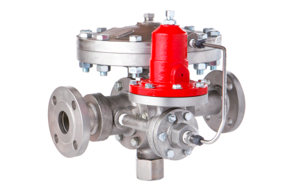
Pneumatic Load cell

Pneumatic Load Cell Principle

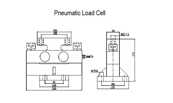
The main parts of a pneumatic load cell are as follows:

  • A corrugated diaphragm with its top surface attached with arrangements to apply force.
  • An air supply regulator, nozzle and a pressure gauge arranged as shown in figure.
  • A flapper arranged above the nozzle as shown in figure.

Operation of Pneumatic Load cell

 The force to be measured is applied to the top side of the diaphragm. Due to this force, the diaphragm deflects and causes the flapper to shut-off the nozzle opening.Now an air supply is provided at the bottom of the diaphragm. As the flapper closes the nozzle opening, a back pressure results underneath the diagram. This back pressure acts on the diaphragm producing an upward force.

Air pressure is regulated until the diaphragm returns to the pre-loaded position which is indicated by air which comes out of the nozzle. At this stage, the corresponding pressure indicated by the pressure gauge becomes a measure of the applied force when calibrated.

Note:

  • The pneumatic load cell can measure loads upto 2.5*10^3 Kgf.
  • The accuracy of this system is 0.5 percent of the full scale.
Don't Miss Our Updates
Be the first to get exclusive content straight to your email.
We promise not to spam you. You can unsubscribe at any time.
Invalid email address
You've successfully subscribed !

Continue Reading

Test Automation in Production Environment – Everything You Should Know
Difference Between CNC Machine and VMC Machine
Pneumatic Instrumentation
Circular Chart Recorder Calibration Procedure
Use of Isolator in Microwaves
Classification of HVAC Chillers
Share This Article
Facebook Whatsapp Whatsapp LinkedIn Copy Link
Share
Leave a Comment

Leave a Reply Cancel reply

Your email address will not be published. Required fields are marked *

Stay Connected

128.3kFollowersLike
69.1kFollowersFollow
208kSubscribersSubscribe
38kFollowersFollow

Categories

Explore More

Types of Tachometers – Mechanical and Electrical Tachometers
CNC Milling versus CNC Turning – Which is the Best Option?
Piping and Instrumentation Drawing (P&ID) Tutorials – Part 2
Car Lifts – Choosing the Right One for Your Mechanic Shop
Most General Reasons for the Electrical Motor Failures
Types of Sensors Used in Automobiles
Computer Science and Technology Majors Certifications
Introduction to the Industrial Internet of Things (IIoT)

Keep Learning

Instrument Skid

What is an Instrument Skid? – Example of Metering Skid

Personal Protection Equipment

What is PPE? – Types – Personal Protection Equipment

Radiation Exposure Converter

Free Online Radiation Exposure Calculating Platform

temperature sensor

Dead time

Classification of Weighing Balance

Classification of Weighing Balance and Weight

Four Wire Current Loop

4-wire Transmitters Current Loops

Hydraulic Systems

What is Hydraulic? Maintenance of Hydraulic Systems

What is a Database Server

What is a Database Server? – Types, Comparison

Learn More

Magnetic Float Level Switch Principle

Magnetic Float Level Switch Installation Techniques

electromechanical-level-measurement-working-principle

ElectroMechanical Level Measurement Working Principle

Seven Segment LED Display

Difference Between Common Cathode and Common Anode 7 Segment LED Display?

DCS Commissioning Steps

DCS Commissioning Steps

Electrical Machines Objective Questions

Electrical Machines MCQ Series 14

Rupture Disc

Rupture Discs bursts caused too many Urea Plant Shutdowns

Control Systems Questions & Answers

Control Systems Objective Questions & Answers – Set 8

Rack Type PLC

PLC Input Output Modules

Follow US
All rights reserved. Reproduction in whole or in part without written permission is prohibited.
Welcome Back!

Sign in to your account

Username or Email Address
Password

Lost your password?