Inst ToolsInst ToolsInst Tools
  • Courses
  • Automation
    • PLC
    • Control System
    • Safety System
    • Communication
    • Fire & Gas System
  • Instrumentation
    • Design
    • Pressure
    • Temperature
    • Flow
    • Level
    • Vibration
    • Analyzer
    • Control Valve
    • Switch
    • Calibration
    • Erection & Commissioning
  • Interview
    • Instrumentation
    • Electrical
    • Electronics
    • Practical
  • Q&A
    • Instrumentation
    • Control System
    • Electrical
    • Electronics
    • Analog Electronics
    • Digital Electronics
    • Power Electronics
    • Microprocessor
Search
  • Books
  • Software
  • Projects
  • Process
  • Tools
  • Basics
  • Formula
  • Power Plant
  • Root Cause Analysis
  • Electrical Basics
  • Animation
  • Standards
  • 4-20 mA Course
  • Siemens PLC Course
Reading: Logic Gates and Truth tables
Share
Notification Show More
Font ResizerAa
Inst ToolsInst Tools
Font ResizerAa
  • Courses
  • Design
  • PLC
  • Interview
  • Control System
Search
  • Courses
  • Automation
    • PLC
    • Control System
    • Safety System
    • Communication
    • Fire & Gas System
  • Instrumentation
    • Design
    • Pressure
    • Temperature
    • Flow
    • Level
    • Vibration
    • Analyzer
    • Control Valve
    • Switch
    • Calibration
    • Erection & Commissioning
  • Interview
    • Instrumentation
    • Electrical
    • Electronics
    • Practical
  • Q&A
    • Instrumentation
    • Control System
    • Electrical
    • Electronics
    • Analog Electronics
    • Digital Electronics
    • Power Electronics
    • Microprocessor
Follow US
All rights reserved. Reproduction in whole or in part without written permission is prohibited.
Inst Tools > Blog > Common > Logic Gates and Truth tables

Logic Gates and Truth tables

Last updated: November 1, 2018 8:40 pm
Editorial Staff
Common
1 Comment
Share
2 Min Read
SHARE

Truth tables offer a simple and easy to understand tool that can be used to determine the output of any logic gate or circuit for all input combinations.

Truth Tables

When a logic gate has only two inputs, or the logic circuit to be analyzed has only one or two gates, it is fairly easy to remember how a specific gate responds and determine the output of the gate or circuit. But as the number of inputs and/or the complexity of the circuit grows, it becomes more difficult to determine the output of the gate or circuit.

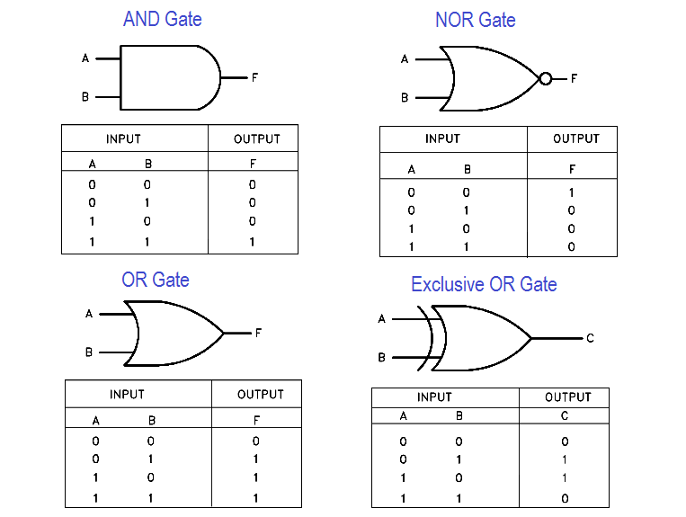
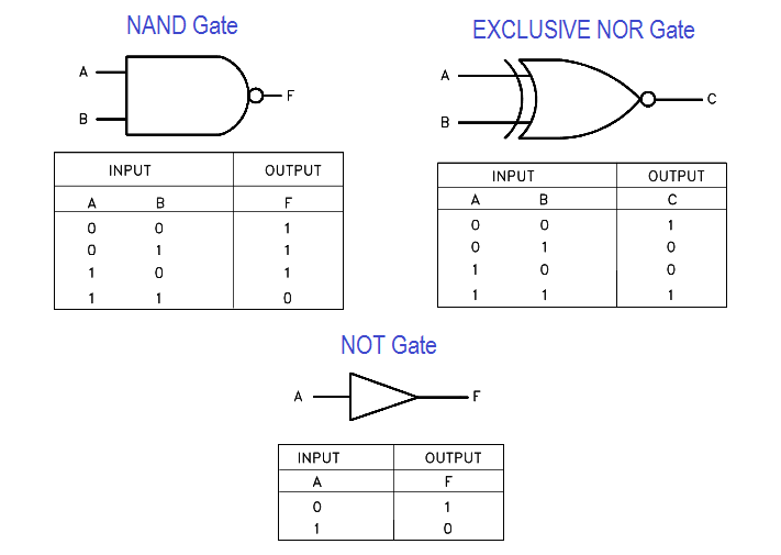
Truth tables, as illustrated in Figure 11, are tools designed to help solve this problem.

A truth table has a column for the input of each gate and column for the output of each gate. The number of rows needed is based on the number of inputs, so that every combination of input signal is listed (mathematically the number of rows is 2 , where n = number of inputs).

In truth tables, the on and off status of the n inputs and outputs is represented using 0s and 1s. As previously stated 0 = off and 1 = on. Figure 11 lists truth tables for the seven basic logic gates. Compare each gate’s truth table with its definition given earlier in this module, and verify for yourself that they are stating the same thing.

Logic Gates and Truth tables

Universal Logic Gates and Truth tables

Figure 11 Truth Tables

Don't Miss Our Updates
Be the first to get exclusive content straight to your email.
We promise not to spam you. You can unsubscribe at any time.
Invalid email address
You've successfully subscribed !

Continue Reading

Imbibition Water Flow Control System – Sugar Factory
Hydraulic Shaper Machine – Components, Circuit, Principle
What is Hydraulic? Maintenance of Hydraulic Systems
What is an Absorption Chiller? – Working Principle
Electrical Torsion Meter Principle
Standard Maintenance Procedure (SMP)
Share This Article
Facebook Whatsapp Whatsapp LinkedIn Copy Link
Share
1 Comment
  • nelly says:
    November 4, 2023 at 6:56 pm

    very good

    Reply

Leave a Reply Cancel reply

Your email address will not be published. Required fields are marked *

Stay Connected

128.3kFollowersLike
69.1kFollowersFollow
210kSubscribersSubscribe
38kFollowersFollow

Categories

Explore More

Piping and Instrumentation Drawing (P&ID) Tutorials – Part 4
Aluminum CNC Machining: A Complete Guide You Cannot Miss
What is a Photoelectric Sensor?
Strain Gauge Load Cell
Circular Chart Recorder Calibration Procedure
The 5 Phases of Conducting Shutdown Maintenance
Electrical Systems vs. Pneumatic Systems
Automation in Farming & Agriculture

Keep Learning

Sheet Metal Fabrication Manufacturing and Design

Ideal Guide To Sheet Metal Fabrication Manufacturing and Design

wash column temperature control

Pneumatic Instrumentation

Types of Angular Velocity Measurement

Types of Angular Velocity Measurement

Flange Types and Definitions

Flange Types and Definitions

Automotive Rail Rapid Transit

Automotive Rail Rapid Transit

CIPP Lining Procedure

What is CIPP Lining? Procedure and Advantages

ISA symbols for Process Instrumentation

ISA Codes & Symbols for Process Instrumentation

Applications of Robots

Applications of Robots in Various Fields

Learn More

High Frequency Amplifiers Objective Questions

High Frequency Amplifiers Objective Questions

Modbus Code

Modbus Relative Addressing

Troubleshooting Fluid Systems Pressure Changes

Troubleshooting Fluid Systems Pressure Changes

How to choose between PLC and DCS Systems

How to choose between PLC and DCS Systems ?

Pull-up switch circuit.

Pull Up and Pull Down Switch Circuits

Principle of ultrasonic testing

Ultrasonic Testing (UT) : Principle, Advantages, Disadvantages

How to use Scale and Normalize Instructions in PLC

Scale and Normalize Instructions in PLC

Shunt-Wound DC Generator Principle

Shunt-Wound DC Generators

Menu

  • About
  • Privacy Policy
  • Copyright

Quick Links

  • Learn PLC
  • Helping Hand
  • Part Time Job

YouTube Subscribe

Follow US
All rights reserved. Reproduction in whole or in part without written permission is prohibited.
Welcome Back!

Sign in to your account

Username or Email Address
Password

Lost your password?