Tubing vs. Pipe
Standard fluid line systems, whether for simple household use or for the more exacting requirements of industry, were for many years constructed from threaded pipe of assorted materials and were assembled with various standard pipe fitting shapes, unions and nipples. Such systems under high pressures were plagued with leakage problems besides being cumbersome, inefficient and costly to assemble and maintain. Therefore, the use of pipe in these systems has largely been replaced by tubing because of the many advantages it offers.
Old Method – Each connection is threaded – requires numerous fittings – system not flexible or easy to install and service connections not smooth inside – pockets obstruct flow.
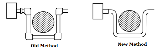
Modern Method – Bendable tubing needs fewer fittings – no threading required – system light and compact – easy to install and service – no internal pockets or obstructions to free flow.
Major Advantages of Tubing vs. Pipe
1. Bending Quality – Tubing has strong but relatively thinner walls; is easy to bend. Tube fabrication is simple.
2. Greater Strength – Tubing is stronger. No weakened sections from reduction of wall thickness by threading.
3. Less Turbulence – Smooth bends result in streamlined flow passage and less pressure drop.
4. Economy of Space and Weight – With its better bending qualities and a smaller outside diameter, tubing saves space and permits working in close quarters. Tube fittings are smaller and also weigh less.
5. Flexibility – Tubing is less rigid, has less tendency to transmit vibration from one connection to another.
6. Fewer Fittings – Tubing bends substitute for elbows. Fewer fittings mean fewer joints, fewer leak paths.
7. Tighter Joints – Quality tube fittings, correctly assembled, give better assurance of leak-free systems.
8. Better Appearance – Tubing permits smoother contours with fewer fittings for a professional look to tubing systems.
9. Cleaner Fabrication – No sealing compounds on tube connections. Again no threading; minimum chance of scale, metal chips, foreign particles in system.
10. Easier Assembly and Disassembly – Every tube connection serves as a union. Tube connections can be reassembled repeatedly with easy wrench action.
11. Less Maintenance – Advantages of tubing and tube fittings add up to dependable, trouble-free installations.
Principles of Tube Line Fabrication
1. Measure Exactly – Bend Accurately
These are the two most important rules which must be observed when fabricating a tube line. Figure 1
EXACT MEASUREMENT is required to insure that you obtain the desired distance between bends. If you do not measure exactly, the tube line will not fit. Figure 2
ACCURATE BENDING is necessary to achieve the exact angles required for the tube line. If you do not bend accurately, the tube line will not fit. (Figure 3)
2. Tube Centerline Basis for Measurement
The centerline of the tube is the basis for all tube line measurement. (Figure 4) Always measure from the centerline except from the first bend which is measured from the end of the tube. On most benders, the edge of the radius block is at the centerline of the tube.
3. You Control Accuracy
Remember only you can control the accuracy of your work. Use good, careful workmanship at all times.
Tube Bending Check list
Follow this list to insure good results on each bend.
1. Measure and mark exactly. Insert tube in bender.
2. Always try to bend in the same direction! If you backbend, be sure to compensate for gain or pickup. Remember, gain always occurs to the right side of the tube radius block.
3. Clamp tubing securely in bender.
4. Check to make certain length mark is tangent to desired angle on radius block or in line with the desired degree on the link member.
5. Bend accurately to the desired angle plus springback allowance.
6. Open bender, remove tube.
7. Double check bend angle with triangle.
8. Check measurement length with tape or ruler.
Keep Track of Changes of Plane
Benders bend in only one direction. Changes in plane are accomplished by rotating the tubing in the bender. To insure that the tubing is correctly placed for the desired change in plane, a reference mark on the tube is very helpful.
Bend Direction Mark
One method for keeping track of changes in plane is to use a longitudinal or lengthwise bend direction mark. (Figure 5) Put the mark on the side opposite the direction in which you wish to bend. When you put the tube in the bender, center the mark face up in the groove of the radius block. (Figure 6) This will insure that you bend in the correct direction. It also gives you a reference mark in case you must leave your work unfinished.
Marking the Tube
Whenever you make a mark on tubing, use a sharp pencil. Use a ferrule as a guide to make measurement marks all the way around the tube so that the mark is always visible. (Figure 7) Don’t use grease pencils or crayons as these make too wide a line which can easily affect accuracy.
Measure and Mark
Never use a sharp tool to scratch marks onto tubing. Scratches create points where corrosion or stress concentration can ruin or dangerously weaken the tube.
Rules for Positioning Tubing in Bender
A line which is tangent to the desired angle mark on the radius block and which passes through the measurement mark at the centerline of the tube, is used to control the distance between bend centerlines. (Figure 8)
Tube Positioning Rules
Compensate for springback
1. Test a piece of the material before you start fabricating a line to see how much it springs back on a 90° bend.
2. Overbend by the amount of springback. For example, if the material springs back 3° on a 90° bend, bend to 93° to secure a finished 90° bend, or to 46-1/2° to obtain finished 45° bend. This works especially well with large heavy-wall tubing.
3. Remember, it is always better to underbend slightly. You can always bend a little more if needed, but it’s almost impossible to remove or straighten a bend, especially with large, heavy-wall tubing.
REMEMBER – A TUBE BENDER BENDS – IT CAN NOT UNBEND.
Also Read: Instrument Tube Fitting Installation – Part 2
In this article, we are going to discuss about shutter door control using induction motor…
Electrical Drives control the motion of electric motors. Motion control is required in industrial and…
PLC ladder logic design to control 3 motors with toggle switch and explain the program…
VFD simulator download: Master the online tool from the Yaskawa V1000 & programming software for…
The conveyor sorting machine is widely used in the packing industries using the PLC program…
Learn the example of flip-flop PLC program for lamps application using the ladder logic to…


