Foundation Fieldbus Pressure Transmitter Configuration
FF Pressure transmitter basic configuration parameters are L_Type, XD_Scale, OUT_Scale and Channel.
These parameters are configured in Analog Input (AI) Function block of FF transmitter.
The below problems shows the pressure transmitter configurations for different cases.
Problem 1 :-
A pressure transmitter with a range of 0 – 100 psi. How to configure a foundation fieldbus pressure transmitter ?
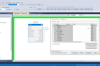
Analog Input function block configuration for a typical pressure transmitter as per below table :
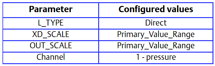
Here Primary_Value_Range : 0 to 100
Problem 2 :-
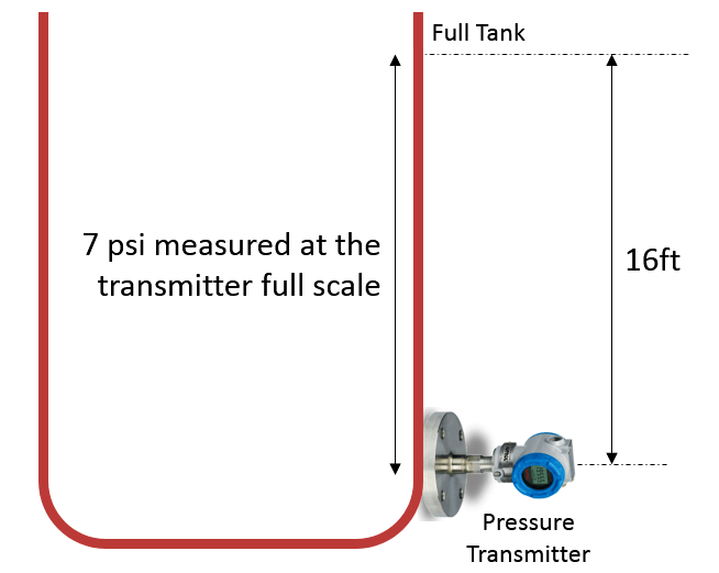
The level of an open tank is to be measured using a pressure tap at the bottom of the tank. The maximum level of the tank is 16 ft. The liquid in the tank has a density that makes the maximum level correspond to a pressure of 7.0 psi at the pressure tap (see below Figure).
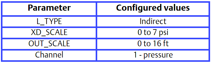
The table below lists the appropriate configuration settings.
Analog Input function block configuration for a pressure transmitter used in level measurement (problem #1).
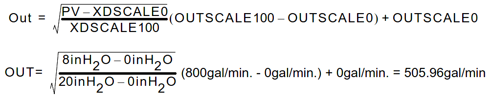
Output calculation for Problem 2 :
When the L_Type is configured as Indirect, the OUT parameter is calculated as:

OUT = [ (PV – XD_SCALE_0% ) / (XD_SCALE_100% – XD_SCALE_0%) ] x ( (OUT_SCALE_100% – OUT_SCALE_0%) + OUT_SCALE_0%)
In this example, when PV is 5 psi, then the OUT parameter will be calculated as follows:
OUT = [ ( 5 psi – 0 psi ) / (7 psi – 0 psi) ] x ((16 ft – 0 ft) + 0 ft ) = 11.43 ft
Problem 3 :-
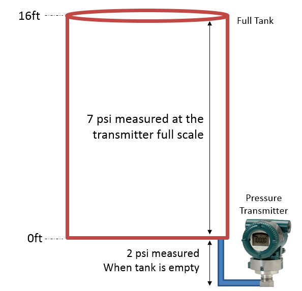
The transmitter in problem #3 is installed below the tank in a position where the liquid column in the impulse line, with an empty tank, is equivalent to 2.0 psi (see Below Figure ).
Solution to Problem #3
The table below lists the appropriate configuration settings.
Analog Input function block configuration for a pressure transmitter used in level measurement (Problem #3).
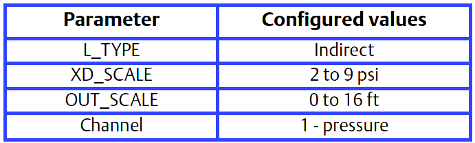
In this example, when the PV is 4 psi, OUT will be calculated as follows:
OUT = [ (4 psi – 2 psi ) / (9 psi – 2 psi) ] x ( (16 ft. – 0 ft.) + 0 ft.) = 4.57 ft.
Differential pressure transmitter to measure flow
Problem 4 :-
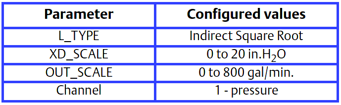
The liquid flow in a line is to be measured using the differential pressure across an orifice plate in the line. Based on the orifice specification sheet, the differential pressure transmitter was calibrated for 0 to 20 inH2O for a flow of 0 to 800 gal/min.
Solution
The table below lists the appropriate configuration settings.
Reference : Rosemount Pressure Transmitter Manual


Excellent document to lean from Pressure Transmitter
Excellent……but plz explain zero elevation ( positive bias ) transmitter configuration
Hi, Already available in “Level Measurement” Category. Please check.
Please share link of it.