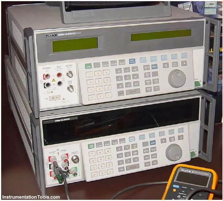
Electrical calibration equipment – used to calibrate instruments measuring voltage, current, and resistance – must be periodically calibrated against higher-tier standards maintained by outside laboratories. In years past, instrument shops would often maintain their own standard cell batteries (often called Weston cells) as a primary voltage reference. These special-purpose batteries produced 1.0183 volts DC at room temperature with low uncertainty and drift, but were sensitive to vibration and non-trivial to actually use. Now, electronic voltage references have all but displaced standard cells in calibration shops and laboratories, but these references must be checked and adjusted for drift in order to maintain their NIST traceability.
One enormous benefit of electronic calibration references is that they are able to generate accurate currents and resistances in addition to voltage (and not just voltage at one fixed value, either!). Modern electronic references are digitally-controlled as well, which lends themselves well to automated testing in assembly-line environments, and/or programmed multi-point calibrations with automatic documentation of as-found and as-left calibration data.
A photograph of some electronic calibration references appears here:

If a shop cannot afford one of these versatile references for benchtop calibration use, an acceptable alternative in some cases is to purchase a high-accuracy multimeter and equip the calibration bench with adjustable voltage, current, and resistance sources. These sources will be simultaneously connected to the high-accuracy multimeter and the instrument under test, and adjusted until the high-accuracy meter registers the desired value. The measurement shown by the instrument under test is then compared against the reference meter and adjusted until matching (to within the required tolerance).
The following illustration shows how a high-accuracy voltmeter could be used to calibrate a handheld voltmeter in this fashion:
It should be noted that the variable voltage source shown in this test arrangement need not be sophisticated. It simply needs to be variable (to allow precise adjustment until the high-accuracy voltmeter registers the desired voltage value) and stable (so the adjustment will not drift appreciably over time). The accuracy of your calibration in the previous circuit originates not from the variable voltage source, but rather from the high-accuracy multimeter used as the calibration standard. It is the high-accuracy multimeter that serves as the calibration reference here, not the voltage source – it is the high-accuracy multimeter that functions as the standard.
The PLC panel and MCC panel interface signals are start, stop, run feedback, trip, local…
In this article, we are going to discuss about shutter door control using induction motor…
Electrical Drives control the motion of electric motors. Motion control is required in industrial and…
PLC ladder logic design to control 3 motors with toggle switch and explain the program…
VFD simulator download: Master the online tool from the Yaskawa V1000 & programming software for…
The conveyor sorting machine is widely used in the packing industries using the PLC program…