Inst ToolsInst ToolsInst Tools
  • Courses
  • Automation
    • PLC
    • Control System
    • Safety System
    • Communication
    • Fire & Gas System
  • Instrumentation
    • Design
    • Pressure
    • Temperature
    • Flow
    • Level
    • Vibration
    • Analyzer
    • Control Valve
    • Switch
    • Calibration
    • Erection & Commissioning
  • Interview
    • Instrumentation
    • Electrical
    • Electronics
    • Practical
  • Q&A
    • Instrumentation
    • Control System
    • Electrical
    • Electronics
    • Analog Electronics
    • Digital Electronics
    • Power Electronics
    • Microprocessor
  • Request
Search
  • Books
  • Software
  • Projects
  • Process
  • Tools
  • Basics
  • Formula
  • Power Plant
  • Root Cause Analysis
  • Electrical Basics
  • Animation
  • Standards
  • 4-20 mA Course
  • Siemens PLC Course
Reading: Diaphragm Pressure Sensors
Share
Font ResizerAa
Inst ToolsInst Tools
Font ResizerAa
  • Courses
  • Design
  • PLC
  • Interview
  • Control System
Search
  • Courses
  • Automation
    • PLC
    • Control System
    • Safety System
    • Communication
    • Fire & Gas System
  • Instrumentation
    • Design
    • Pressure
    • Temperature
    • Flow
    • Level
    • Vibration
    • Analyzer
    • Control Valve
    • Switch
    • Calibration
    • Erection & Commissioning
  • Interview
    • Instrumentation
    • Electrical
    • Electronics
    • Practical
  • Q&A
    • Instrumentation
    • Control System
    • Electrical
    • Electronics
    • Analog Electronics
    • Digital Electronics
    • Power Electronics
    • Microprocessor
  • Request
Follow US
All rights reserved. Reproduction in whole or in part without written permission is prohibited.
Inst Tools > Blog > Pressure Measurement > Diaphragm Pressure Sensors

Diaphragm Pressure Sensors

Last updated: May 16, 2018 3:58 pm
Editorial Staff
Pressure Measurement
1 Comment
Share
3 Min Read
SHARE

The Diaphragm Pressure Gauge uses the elastic deformation of a diaphragm (i.e. membrane) instead of a liquid level to measure the difference between an unknown pressure and a reference pressure.

A typical Diaphragm pressure gauge contains a capsule divided by a diaphragm, as shown in the schematic below. One side of the diaphragm is open to the external targeted pressure, PExt, and the other side is connected to a known pressure, PRef,. The pressure difference, PExt – PRef, mechanically deflects the diaphragm.

diaphragm-pressure-gauge


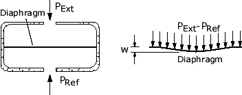
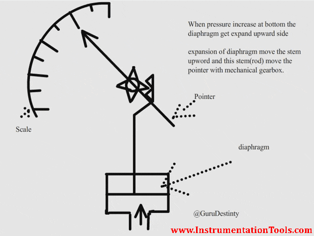
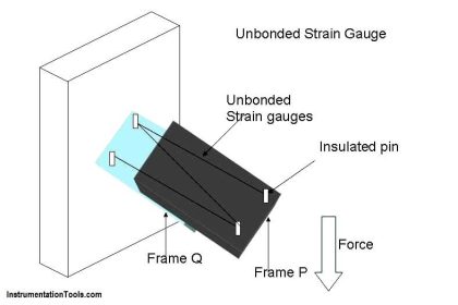
The membrane deflection can be measured in any number of ways. For example, it can be detected via a mechanically-coupled indicating needle, an attached strain gage, a linear variable differential transformer(LVDT; see the schematic below), or with many other displacement/velocity sensors. Once known, the deflection can be converted to a pressure loading using plate theory.

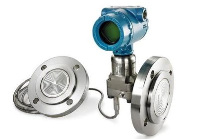
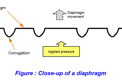
Many pressure sensors depend on the deflection of a diaphragm for measurement. The diaphragm is a flexible disc, which can be either flat or with concentric corrugations and is made from sheet metal with high tolerance dimensions.

The diaphragm can be used as a means of isolating the process fluids, or for high- pressure applications. It is also useful in providing pressure measurement with electrical transducers.

diaphragm-pressure-sensor-animation

Diaphragms are well developed and proven. Modern designs have negligible hysteresis, friction and calibration problems when used with smart instrumentation.

They are used extensively on air conditioning plants and for ON/OFF switching applications.

Selection

The selection of diaphragm materials is important, and are very much dependent on the application.  Beryllium copper has good elastic qualities, where Ni-Span C has a very low temperature coefficient of elasticity.

Stainless steel and Inconel are used in extreme temperature applications, and are also suited for corrosive environments.  For minimum hysteresis and drift, then Quartz is the best choice.

There are two main types of construction and operation of diaphragm sensors.  They are:

– Motion Balanced

– Force Balanced

Motion balanced designs are used to control local, direct reading indicators.  They are however more prone to hysteresis and friction errors.

Force balanced designs are used as transmitters for relaying information with a high accuracy, however they do not have direct indication capability.

Advantages

  • Provide isolation from process fluid
  • Good for low pressure
  • Wide range
  • Reliable and proven
  • Used to measure gauge, atmospheric and differential pressure

Cons

  • More expensive then other pressure sensors.
Don't Miss Our Updates
Be the first to get exclusive content straight to your email.
We promise not to spam you. You can unsubscribe at any time.
Invalid email address
You've successfully subscribed !

Continue Reading

Capacitive Type Pressure Transducers Principle
3 Valve Manifold Operation
Differential Pressure Transmitter Working Principle
How to Read Gauge Analog Scales
Questions on Pressure Transmitter Calibration Setup
Pressure Measurement Objective Questions
Share This Article
Facebook Whatsapp Whatsapp LinkedIn Copy Link
Share
1 Comment
  • Ramesh Kumar says:
    October 22, 2020 at 7:55 am

    I did not find any statement on accuracy of instrument.

    Reply

Leave a Reply Cancel reply

Your email address will not be published. Required fields are marked *

Stay Connected

128.3kFollowersLike
69.1kFollowersFollow
210kSubscribersSubscribe
38kFollowersFollow

Categories

Explore More

Pressure Switch Calibration Procedure
Pressure Gauge Snubbers
Bourdon Tube Pressure Gauge
Capillary Tubing Pressure Sensor Temperature & Elevation Problems
Information on the Pressure Gauge Dial
Differential Pressure Sensor for Filtration Monitoring
Pressure Gauges with Capsule Sensor Principle
Troubleshooting Fluid Systems Pressure Changes

Keep Learning

Pressure Transmitter Working Principle

Gage and Absolute Pressure Transmitters Principle

Magnehelic Gauge Calibration

Magnehelic Gauge Calibration

inductance transducer

Inductance Type Pressure Transducers Principle

Two-Liquid Manometer Principle

Two-Liquid Manometer Principle

Impulse Line Problems

What are Impulse Lines? – Impulse Line Problems & Solutions

The Principle of Dead Weight Pressure Tester

The Principle of Dead Weight Pressure Tester

Sealed Bellows Temperature Sensors

Bellows Pressure Sensors Working Principle Animation

Pressure Measurement using Manometer

Pressure Measurement using Manometer

Learn More

Voltage Control Methods at Distribution System

Factors affect Voltage Level Selection in Service System

Rotary Lobe Air Compressor

Centrifugal Compressors

Remote Seals Transmitters Temperature Error

Remote Seal Transmitters Temperature Error

Mixing Process with Valve Control

PLC Mixing Process with Adjustable Timer and Valve Control

Vision Camera System

Vision Camera Systems in Industrial Automation

DC motor speed control

DC Motor Speed Control

Spectrometers Questions and Answers

X-Ray Fluorescence Spectrometry Questions and Answers

How Does an Infrared Thermometer Work

How Does an Infrared Thermometer Work?

Menu

  • About
  • Privacy Policy
  • Copyright

Quick Links

  • Learn PLC
  • Helping Hand
  • Part Time Job

YouTube Subscribe

Follow US
All rights reserved. Reproduction in whole or in part without written permission is prohibited.
Welcome Back!

Sign in to your account

Username or Email Address
Password

Lost your password?