Here we are discussing about how to convert smart transmitter HART type output current 4-20ma into foundation fieldbus signal.
The block diagram for connecting smart transmitter to FF device.
 |
| Terminal Diagram with 4-20 mA Conversion to 20-100 mV |
First we need to convert the 4-20ma output of a smart transmitter to 20-100 mv signal. To convert ma into mv signal we need a precise 5 ohm resistor. The resistor to be connected in series in the 4-20ma transmitter.Then a FF device must be connected across the resistor. The FF device tag assignment and block configuration are common procedures only. Then the FF device reads the 20-100 mv signal then indicates the corresponding values in the field as well as in control room DCS.
This technique should not be applied to a 4-20 mA source that is actively connected to a loop control. The 5 ohm resistor must be installed before powering up the transmitter. Do not apply the mA source directly to the transmitter’s millivolt terminals; applying directly to the mV terminals without the resistor may damage the electronics. Do not allow the voltage to exceed 100 mV. Exceeding 100mV voltage in the loop could potentially damage the transmitter.
 |
|
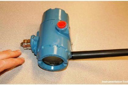
Wiring diagram for Rosemount 3051SMV converted into FOUNDATION Fieldbus signal
|
SIGNAL CONVERSION: The 644 measures millivolt signals. To monitor a 4-20 mA signal, a conversion to millivolt will be required using a 5 Ohm resistor. A 5 ohm resistor will convert the 4-20 mA signal to a 20-100 mV signal. It is optimal to use a low-error 5 Ohm resistor with stable operation rating across the ambient temperature range in which the 644 is installed.
ROSEMOUNT 644 CONFIGURATION
Configuration of the 644 can be performed using a Handheld Field Communicator or AMS Device Manager. Configure the sensor type and device units to “mV.” Configure the AI block of the 644 as follows:
1. Set the MODE_BLK.TARGET to OOS
2. Set CHANNEL to the transducer block configured for the analog input
3. Set XD_SCALE.EU_0 to 20 Set XD_SCALE.EU100 to 100
Set XD_SCALE.ENGUNITS to mV
4. Set OUT_SCALE to match the desired scale and units for the connected analog transmitter.
5. Flow Example: 0-200 gpm OUT_SCALE.EU_0 = 0 OUT_SCALE.EU_100 = 200 OUT_SCALE.ENGUNITS = gpm
6. Set L_TYPE to INDIRECT
7. Set the MODE_BLK.TARGET to AUTO
Also Read: Foundation Fieldbus Principles


well i really dont know how to convert hart to FF but you solved my problem.
Thanks for the description.
Is there any device to convert FF signal to 4 to 20 ma or 1 To 5 V DC
In the 2nd figure, you have connected 5ohm resistor in parallel not in series, but in the first figure its connected in series.
Hi, in both figures the 5 Ohm precision resistor is connected in parallel of the Fieldbus Foundation (FF) device and in series within the Hart loop.