Inst ToolsInst ToolsInst Tools
  • Courses
  • Automation
    • PLC
    • Control System
    • Safety System
    • Communication
    • Fire & Gas System
  • Instrumentation
    • Design
    • Pressure
    • Temperature
    • Flow
    • Level
    • Vibration
    • Analyzer
    • Control Valve
    • Switch
    • Calibration
    • Erection & Commissioning
  • Interview
    • Instrumentation
    • Electrical
    • Electronics
    • Practical
  • Q&A
    • Instrumentation
    • Control System
    • Electrical
    • Electronics
    • Analog Electronics
    • Digital Electronics
    • Power Electronics
    • Microprocessor
  • Request
Search
  • Books
  • Software
  • Projects
  • Process
  • Tools
  • Basics
  • Formula
  • Power Plant
  • Root Cause Analysis
  • Electrical Basics
  • Animation
  • Standards
  • 4-20 mA Course
  • Siemens PLC Course
Reading: Controllability & Observability
Share
Font ResizerAa
Inst ToolsInst Tools
Font ResizerAa
  • Courses
  • Design
  • PLC
  • Interview
  • Control System
Search
  • Courses
  • Automation
    • PLC
    • Control System
    • Safety System
    • Communication
    • Fire & Gas System
  • Instrumentation
    • Design
    • Pressure
    • Temperature
    • Flow
    • Level
    • Vibration
    • Analyzer
    • Control Valve
    • Switch
    • Calibration
    • Erection & Commissioning
  • Interview
    • Instrumentation
    • Electrical
    • Electronics
    • Practical
  • Q&A
    • Instrumentation
    • Control System
    • Electrical
    • Electronics
    • Analog Electronics
    • Digital Electronics
    • Power Electronics
    • Microprocessor
  • Request
Follow US
All rights reserved. Reproduction in whole or in part without written permission is prohibited.
Inst Tools > Blog > Multiple Choice Questions > Controllability & Observability

Controllability & Observability

Last updated: November 27, 2021 5:40 pm
Editorial Staff
Multiple Choice Questions
No Comments
Share
4 Min Read
SHARE

Controllability & Observability

1. A system is said to be_____________ if it is possible to transfer the system state from any initial state to any desired state in finite interval of time.

a) Controllable
b) Observable
c) Cannot be determined
d) Controllable and observable

Answer: a

Explanation: By definition a system is said to be controllable, if it is possible to transfer the system state from any initial state to any desired state in finite interval of time.

2. A system is said to be_________________ if every state can be completely identified by measurements of the outputs at the finite time interval.

a) Controllable
b) Observable
c) Cannot be determined
d) Controllable and observable

Answer: b

Explanation: By definition, a system is said to be observable, if every state can be completely identified by measurements of the outputs at the finite time interval.

3. Kalman’s test is for :

a) Observability
b) Controllability
c) Optimality
d) Observability and controllability

Answer: d

Explanation: Kalman’s test is the test that is done for the controllability and observability by solving the matrix by kalman’s matrix individually for both tests.

4. Consider a system if represented by state space equation and x1 (t) =x2 (t), then the system is:

a) Controllable
b) Uncontrollable
c) Observable
d) Unstable

Answer: b

Explanation: After calculating the matrix which for controllable system and finding the determinant and should not be zero but in this case comes to be zero.

5. For the system,

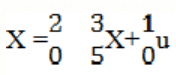
which of the following statements is true?

a) The system is controllable but unstable
b) The system is uncontrollable and unstable
c) The system is controllable and stable
d) The system is uncontrollable and stable

Answer: b

Explanation: By Kalman’s stability test the system is uncontrollable and root of the characteristic equation lies on the right side of the s-plane.

6. A transfer function of the system does not have pole-zero cancellation? Which of the following statements is true?

a) System is neither controllable nor observable
b) System is completely controllable and observable
c) System is observable but uncontrollable
d) System is controllable and unobservable

Answer: b

Explanation: If the transfer function of the system does not have pole-zero cancellation then it is completely controllable and observable.

7. Complex conjugate pair:

a) Center
b) Focus point
c) Saddle point
d) Stable node

Answer: b

Explanation: Complex conjugate pair is the complex pair of the roots of the equation and has a focus point.

8. Pure imaginary pair:

a) Centre
b) Focus point
c) Saddle point
d) Stable node

Answer: a

Explanation: Pure imaginary pair is the nature of the root of the equation that has no real part only has the nature of center for linearized autonomous second order system.

9. Real and equal but with opposite sign.

a) Center
b) Focus point
c) Saddle point
d) Stable node

Answer: c

Explanation: Saddle point are real and equal with opposite sign and these points are called the saddle point as the points are different with real and equal with opposite sign.

10. Real distinct and negative.

a) Center
b) Focus point
c) Saddle point
d) Stable node

Answer: d

Explanation: Stable node is real distinct and negative and this node is stable as the points or roots are real and neative lying on the left side of the plane.

Don't Miss Our Updates
Be the first to get exclusive content straight to your email.
We promise not to spam you. You can unsubscribe at any time.
Invalid email address
You've successfully subscribed !

Continue Reading

Process Control Questions & Answers
Thermal Conductivity Analyzers Questions & Answers
Controller Components – Part 2 Objective Questions
Differential Equations of Physical Systems & Dynamics of Robotic Mechanisms
Construction of Phase -Trajectories
Liquid Chromatograph- Mass Spectrometer
Share This Article
Facebook Whatsapp Whatsapp LinkedIn Copy Link
Share
Leave a Comment

Leave a Reply Cancel reply

Your email address will not be published. Required fields are marked *

Stay Connected

128.3kFollowersLike
69.1kFollowersFollow
210kSubscribersSubscribe
38kFollowersFollow

Categories

Explore More

Feedback Control Loop Questions & Answers
Feedback Compensation
Quadrupole Mass Spectrometer
Preliminary Considerations of Classical Design
Process Pressure Measurement Objective Questions
PLC Interview Questions and Answers
Robotic Control System – Part II
Nuclear Magnetic Resonance Spectrometer Questions & Answers

Keep Learning

Root Locus Concepts Objective Questions

Root Locus Concepts Objective Questions

Pressure Measurement Multiple Choice Questions

State Variable Analysis and Design

Solution of State Equations

IR Instrumentation Questions & Answers

IR Instrumentation Questions & Answers

Optimal Control Systems

Optimal Control Problems – Part 2

Time Response Analysis

Robotic Control System – Part I

Absorption Instrumentation Questions & Answers

Absorption Instrumentation Questions & Answers

Ion Analyzers Questions and Answers

Ion Selective Electrodes Questions and Answers

Learn More

Types of Tank Gauging Level Measurement Systems

Types of Tank Gauging Level Measurement Systems

PLC Program for Water filling and Discharging Process

PLC Program for Water filling and Discharging Process

Calculate Hydraulic Pressure of a Drum

Calculate Hydraulic Pressure of a Process Vessel

Analog Electronics Objective Questions

Analog Electronics Objective Questions – Set 7

Resistance Temperature Detectors Troubleshooting Tips

Resistance Temperature Detectors Troubleshooting Tips

deadweight tester principle

Pressure Standards

What is a Differential Mode Signal

Difference Between Differential Mode and Common Mode

Omron PLC painting program

Product Painting PLC Program using Omron CX-Programmer

Menu

  • About
  • Privacy Policy
  • Copyright

Quick Links

  • Learn PLC
  • Helping Hand
  • Part Time Job

YouTube Subscribe

Follow US
All rights reserved. Reproduction in whole or in part without written permission is prohibited.
Welcome Back!

Sign in to your account

Username or Email Address
Password

Lost your password?