Inst ToolsInst ToolsInst Tools
  • Courses
  • Automation
    • PLC
    • Control System
    • Safety System
    • Communication
    • Fire & Gas System
  • Instrumentation
    • Design
    • Pressure
    • Temperature
    • Flow
    • Level
    • Vibration
    • Analyzer
    • Control Valve
    • Switch
    • Calibration
    • Erection & Commissioning
  • Interview
    • Instrumentation
    • Electrical
    • Electronics
    • Practical
  • Q&A
    • Instrumentation
    • Control System
    • Electrical
    • Electronics
    • Analog Electronics
    • Digital Electronics
    • Power Electronics
    • Microprocessor
  • Request
Search
  • Books
  • Software
  • Projects
  • Process
  • Tools
  • Basics
  • Formula
  • Power Plant
  • Root Cause Analysis
  • Electrical Basics
  • Animation
  • Standards
  • 4-20 mA Course
  • Siemens PLC Course
Reading: Closed-Loop Frequency Response
Share
Font ResizerAa
Inst ToolsInst Tools
Font ResizerAa
  • Courses
  • Design
  • PLC
  • Interview
  • Control System
Search
  • Courses
  • Automation
    • PLC
    • Control System
    • Safety System
    • Communication
    • Fire & Gas System
  • Instrumentation
    • Design
    • Pressure
    • Temperature
    • Flow
    • Level
    • Vibration
    • Analyzer
    • Control Valve
    • Switch
    • Calibration
    • Erection & Commissioning
  • Interview
    • Instrumentation
    • Electrical
    • Electronics
    • Practical
  • Q&A
    • Instrumentation
    • Control System
    • Electrical
    • Electronics
    • Analog Electronics
    • Digital Electronics
    • Power Electronics
    • Microprocessor
  • Request
Follow US
All rights reserved. Reproduction in whole or in part without written permission is prohibited.
Inst Tools > Blog > Multiple Choice Questions > Closed-Loop Frequency Response

Closed-Loop Frequency Response

Last updated: November 27, 2021 5:40 pm
Editorial Staff
Multiple Choice Questions
No Comments
Share
4 Min Read
SHARE

Closed-Loop Frequency Response

1. Closed loop frequency response is very useful as :

a) It approximately predicts the time response of the systems
b) Time response are converted into time domain specifications
c) After design time domain specification is converted into frequency domain
d) All of the mentioned

Answer: d

Explanation: Closed loop frequency response is very useful as it enables to use second order correlations between frequency and transient response.

2. Maximum peak overshoot in time domain corresponds to :

a) Resonance peak
b) Resonant frequency
c) Bandwidth
d) Cut-off rate

Answer: a

Explanation: Resonance peak in frequency domain correspond to maximum peak overshoot in time domain.

3. Frequency of oscillation in time domain correspond to :

a) Resonance peak
b) Resonant frequency
c) Bandwidth
d) Cut-off rate

Answer: b

Explanation: Resonant frequency in frequency domain correspond to frequency of oscillation in time domain.

4. Bandwidth is :

a) Range of frequencies for which the system gain is more than-3dB
b) This is considered good range for transmission of signals
c) For better communication bandwidth of signal must be less
d) All of the mentioned

Answer: d

Explanation: Bandwidth of a signal must be less but channel must be more foe better transmission or communication.

5. Cut-off rate is the ability of the system to distinguish the signal from _____________

a) Bandwidth
b) Noise
c) Resonance peak
d) Magnitude

Answer: b

Explanation: Cut-off rate is the ability of the system to distinguish the signal from noise.

6. The important figures of merit to the system in frequency domain are :

a) Maximum value of resonant peak
b) Value of resonance frequency
c) Maximum value of resonant peak and Value of resonance frequency
d) Minimum value of resonance frequency

Answer: c

Explanation: The important figures of merit to the system in frequency domain are maximum value of resonance peak and frequency at which it occurs.

7. In q(s) plane Nyquist plot is symmetrical about the :

a) Imaginary axis
b) Real axis
c) Origin
d) None of the mentioned

Answer: b

Explanation: By definition, In q(s) plane Nyquist plot is symmetrical about the real axis.

8. A polar plot intersects the unit circle at a point making -45° to the negative real axis then the phase margin of the system is :

a) -45°
b) 45°
c) 180°-45°
d) 180°+45°

Answer: b

Explanation: As the angle is with the negative real axis hence the Phase margin will be 45°.

9. The parameter which is constant along the constant N circle :

a) Frequency
b) Phase angle
c) Magnitude
d) Open loop gain

Answer: b

Explanation: Phase angle remains constant in constant N-circle.

10. In second order system gain margin is :

a) Zero value
b) Finite value
c) Infinite value
d) None of the mentioned

Answer: c

Explanation: Gain margin is defined generally for systems with order greater than 3.

Don't Miss Our Updates
Be the first to get exclusive content straight to your email.
We promise not to spam you. You can unsubscribe at any time.
Invalid email address
You've successfully subscribed !

Continue Reading

Flame Emission Photometers Questions & Answers
Common Physical Nonlinearities
All-pass & Minimum-phase Systems
Control Systems Multiple Choice Questions
Feedback Compensation
Carbon Monoxide Questions & Answers
Share This Article
Facebook Whatsapp Whatsapp LinkedIn Copy Link
Share
Leave a Comment

Leave a Reply Cancel reply

Your email address will not be published. Required fields are marked *

Stay Connected

128.3kFollowersLike
69.1kFollowersFollow
210kSubscribersSubscribe
38kFollowersFollow

Categories

Explore More

Level Measurement Multiple Choice Questions
IR Instrumentation Questions & Answers
State Models for Linear Continuous Time Systems
Components of Mass Spectrometer Questions & Answers
Detection System of Gas Chromatography Questions and Answers
MCQ on Measurement and Instrumentation
Ammonia and Fluoride Electrode Questions & Answers
PLC Interview Questions and Answers

Keep Learning

Nonlinear Control Systems

Stability Analysis by Describing Functions

Digital Control Systems

Difference Equations

Ion Spectrometers Questions & Answers

Instrumentation of Ion Spectroscopy

Transformers Interview Questions & Answers

Measurement and Instrumentation Objective Questions – Part 2

Top 1000 Analytical Instrumentation Questions & Answers

Top 1000 Analytical Instrumentation Questions & Answers

pH Analyzers Questions and Answers

Hydrogen and Glass Electrodes Questions & Answers

Pressure Measurement Multiple Choice Questions

Temperature Measurement Multiple Choice Questions

Temperature Measurement Multiple Choice Questions

Learn More

Advantages & Disadvantages Induction Motor

Fire Hydrant System

Basics of Fire Fighting Hydrant Systems

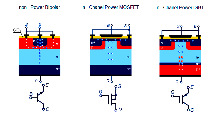
Comparison of MOSFET and BJT

Comparison of MOSFET and BJT

Top 100 Microcontrollers Project Ideas

Top 100 Microcontrollers Project Ideas

DOL Starter Testing

DOL Starter – Working, Circuit, Advantages, Disadvantages, Applications

How to Do Maintenance of Control Valve Which is Stuck in Field?

How to Do Maintenance of Control Valve Which is Stuck in Field?

Bently Nevada 3500 Machinery Protection Systems

Bently Nevada 3500 Machinery Protection Systems Hardware Modules

Solenoid

Difference between AC and DC Solenoid Valves

Menu

  • About
  • Privacy Policy
  • Copyright

Quick Links

  • Learn PLC
  • Helping Hand
  • Part Time Job

YouTube Subscribe

Follow US
All rights reserved. Reproduction in whole or in part without written permission is prohibited.
Welcome Back!

Sign in to your account

Username or Email Address
Password

Lost your password?