How to calibrate the transmitter with a remote seal differential which is implemented in level measurement.Actually, not like where I calibrate the detailed step by step (usually with a HART Communicator), which will be discussed in this post is how to determine the calibration parameters, so that the transmitter works on a range that we want according to the process conditions. But, prior to the calculation method determines the LRV and URV, let us recognize the term first.
There are two terms commonly used in the calibration of the level transmitter with differential transmitter:
Zero Suppression
Zero suppressed required if the transmitter pressure gauge or absolute installed under tapping the side of the high pressure (the bottom side of the process connection). If the transmitter is mounted below the tapping side of the high pressure, the liquid filler (fill fluid) in the capillary puts pressure on the sensor transmitter so as to provide a positive pressure reading even if the tank is empty.
Zero Elevation
Instead, Elevated Zero is required if the pressure gauge or absolute transmitter mounted above the high pressure tapping side (bottom side of the process connection) or on the application of the twoseal differential transmitter (low side and high side). In this case, the transmitter reads a negative pressure when the tank is empty though. This is caused by the effect of head pressure on the fluid filler (fill fluid) on the remote seal capillary tube.
Calibrating Transmitter System One Seal with suppressed Zero done if the transmitter is installed below the tapping point the high pressure side as shown below
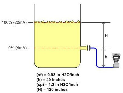
From the picture above, it is known an open tank level is measured by a level transmitter that uses a single remote seal.
(s f) = specific gravity of the fill fluid (liquid filler in the capillary of remote seal)
(h) = the distance between the process of tapping points to the transmitter.
(s p) = specific gravity of process media that are in the tank.
(H) = The range of levels to be measured.
step 1
Calculate the amount of zero suppression by multiplying the distance between the process connection and the transmitter (h) by gravity liquid filler specifiec remote regret (s f):
Zero Suppression = (h) (s f) = (40 in) (0.93 INH 2 O / in) = 37.2 INH 2 O
Step 2
Calculate the span by multiplying the level range to be measured (H) by the specific gravity of the media that are in the process tanki.specific gravity (s p):
Span = (H) (s p) = (120 in) (1.2 INH 2 O / in) = 144 INH 2 O
Step 3
Determine / calculate calibration for the transmitter, which results in step 1 (zero suppression) as the LRV (Lower Range Value) and results in step 1 plus results in step 2 as the URV (Upper Range Value.
Calibration = “Zero Suppression” until (“Zero Suppression” + “Span”)
= 37.2 INH 2 O to (37.2 + 144) INH 2 O
INH 2 O = 37.2 to 181.2 INH 2 O
Conclusion
So, we calibrate the transmitter with:
LRV = 37.2 INH 2 O
URV = 181.2 INH 2 O
Calibration is performed if the transmitter is mounted above (higher than) the high side tap
Is known:
(s f) = 1.9 in H 2 O / inch
(h) = -30 inches
(s p) = 1.1 in H 2 O / inch
(H) = 120 inches
From the picture above, it is known an open tank level measured her with a transmitter that uses a single remote seal with a transmitter is placed on the high side tapping point.
(s f) = specific gravity of the fill fluid (liquid filler in the capillary of remote seal)
(h) = the distance between the process of tapping points to the transmitter (note the minus sign).
(s p) = specific gravity of process media that are in the tank.
(H) = The range of levels to be measured.
step 1
Calculate the amount of zero elevation by multiplying the distance between the process connection and the transmitter (h) by the specific gravity liquid filler remote regret (s f):
Zero Suppression = (h) (s f) = (-30 in) (1.9 INH 2 O / in) = -57 INH 2 O
Step 2
Calculate the span by multiplying the level range to be measured (H) by the specific gravity of the process media are in the tank, pecific gravity (s p):
Span = (H) (s p) = (120 in) (1.1 INH 2 O / in) = 132 INH 2 O
Step 3
Determine / calculate calibration for the transmitter, which results in step 1 (zero elevation) as the LRV (Lower Range Value) and results in step 1 plus results in step 2 as the URV (Upper Range Value).
Calibration = “Elevation Zero” until (“ZeroElevation” + “Span”)
= -57 INH 2 O to (-57 + 132) INH 2 O
= -57 INH 2 O to 75 INH 2 O
Conclusion
So, we calibrate the transmitter with:
LRV = -57 INH 2 O
URV = 75 INH 2 O
This calibration is done if a transmitter with two seal system installed one tapping point level with or above or below the high pressure tap side.
Is known:
(Sf) = 1:07 in H2O / inch
(h) = – 400 inches
(Sp) = 0.9 in H2O / inch
(H) = 350 inches
From the picture above, it is known an open tank level measured her with a transmitter that uses two remote seals each for high and low pressure side of his, the transmitter is placed under the high side tapping point.
(s f) = specific gravity of the fill fluid (liquid filler in the capillary of remote seal)
(h) = the distance between the process of tapping points to the transmitter (note the minus sign).
(s p) = specific gravity of process media that are in the tank.
(H) = The range of levels to be measured.
step 1
Calculate the amount of zero elevation by multiplying the distance between the process connection and the transmitter (h) by gravity liquid filler specifiec remote regret (s f):
Zero Elevation = – (h) (s f) = – (400 in) (1:07 INH 2 O / in) = -428 INH 2 O
Step 2
Calculate the span by multiplying the maximum height of the process fluid (H) by the specific gravity of the process media are in the tank, specific gravity (s p):
Span = (H) (s p) = (350 in) (0.9 INH 2 O / in) = 315 INH 2 O
Step 3
Determine / calculate calibration for the transmitter, which results in step 1 (zero elevation) as the LRV (Lower Range Value) and results in step 1 plus results in step 2 as the URV (Upper Range Value).
Calibration = “Elevation Zero” until (“Elevation Zero” + “Span”)
= -428 INH 2 O until the (-428 + 315) INH 2 O
= -428 To -113 INH INH 2 O 2 O
Conclusion
So, we calibrate the transmitter with:
LRV = -428 INH 2 O
URV = -113 INH 2 O
Also Read: Importance of 4-20mA Current Loop
This PLC example on manufacturing line assembly is an intermediate-level PLC program prepared for the…
In this article, you will learn the PLC programming example with pushbutton and motor control…
This article teaches how to convert Boolean logic to PLC programming ladder logic with the…
In this article, you will learn the PLC programming example on timers function block using…
Design a program for PLC pump control such that the pump must be turned ON…
Polyvinyl alcohol (PVA) is a water-soluble and biodegradable synthetic polymer used in oil field cementing…


View Comments
Thanks. I have no words for this superb website. How can I contact you Mr. Bharadwaj? Really awesome job.
Hello Akshay, You can contact me by mail at instrumentationtools@gmail.com
I am Instrument Engineer. Thanks
Thanks to everyone who involved in this website really sir it's very owesome & very useful again I want to say many many thanks.
Amazing, can u explain that calibration methode suppresed zero is similar with steam drum level calibration?. Thanks
Hi, For Boiler Drum Level Calibration Click Here
I'm instrument technician.. This is very helpful... Thanks
Do you have a 3 element closed loop drawing for steam boiler instrumentation ?
For Boiler Three Element Control Please Click Here
Hi I'm female instrument technician. Really helpful info.. keep that good work sir..
Really good website this one ,how can i download this document
Hello, Please Open website in Desktop/PC and Click on Print Button available under the article heading to save in PDF. Thanks
dear sir
In above closed tank u have mentioned there as elevated zero,,,shouldnt be suppresed zero because transmitter is below hp side
second thing below (3) u mentioned
**From the picture above,it is known OPEN tank level........ i think it should be closed instead of open
am i right?
Its really useful. What will be the formulas to calculate LRV and URV if it is direct flanged in HP and LP side is capillary connection.
Hi, Please check Level Measurement Category. Its available. Regards.